Eureka AIR delivers breakthrough ideas for toughest innovation challenges, trusted by R&D personnel around the world.

A jig for machining a gear shaft

A gear shaft and fixture technology, which is applied in the direction of manufacturing tools, metal processing equipment, metal processing machinery parts, etc., can solve the problems of keyway misalignment, gear shaft rotation, etc., to reduce the probability of rotation, strengthen the clamping effect, reduce the The effect of the risk of keyway misalignment

Active Publication Date: 2021-07-09
浙江三欢齿轮有限公司
View PDF11 Cites 0 Cited by
  • Summary
  • Abstract
  • Description
  • Claims
  • Application Information

AI Technical Summary

Problems solved by technology

[0004] In view of the above-mentioned related technologies, in the process of clamping the gear shaft, the two ends of the gear shaft are clamped by the first center and the second center, so as to achieve the purpose of clamping the gear shaft, but in the process of machining the keyway , there is a risk of the gear shaft turning and thus the risk of misalignment of the machined keyway

Method used


Image

  • A jig for machining a gear shaft
  • A jig for machining a gear shaft
  • A jig for machining a gear shaft

Examples


Embodiment Construction

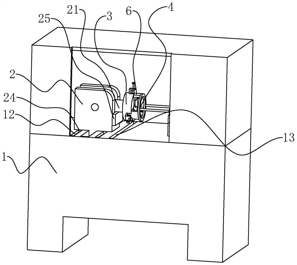
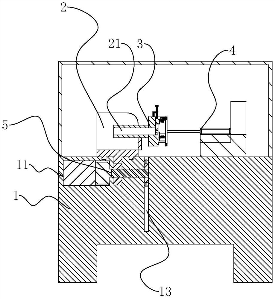
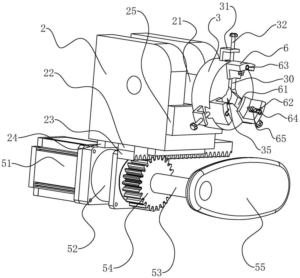
[0033] The following is attached Figure 1-6 The application is described in further detail.

[0034] The embodiment of the present application discloses a jig for gear shaft processing, see figure 1 , including a workbench 1 and a sliding seat 2 arranged on the workbench 1, the slide block 2 is fixedly connected with a slider 24, and the workbench 1 is provided with a chute 12 matching the slider 24, and the slider 24 can slide in the chute 12, and the sliding seat 2 is also hinged with a rotating shaft 21, and the sliding seat 2 is also provided with a support block 25 for supporting the rotating shaft 21, and the supporting block 25 is located below the rotating shaft 21, so as to The rotating shaft 21 is kept horizontal, and one end of the rotating shaft 21 is fixedly connected with a chuck 3 for clamping the gear shaft.

[0035] see figure 2 and image 3, the workbench 1 is provided with a driving mechanism 5 for driving the sliding seat 2 to slide, the workbench 1 i...


PUM


Abstract

The present application relates to a gear shaft processing fixture, which relates to the field of gear processing equipment, which includes a workbench and a chuck arranged on the workbench, the chuck is provided with at least two clamping mechanisms, and the The clamping mechanism includes a clamping block, a positioning rod and a stopper for limiting the position of the clamping block, the clamping block and the chuck are slidably connected, the positioning rod and the clamping block connected, the chuck is provided with a positioning hole, the distance between the adjacent clamping blocks is equal, the clamping block is arc-shaped and concentric with the positioning hole, and the The positioning rod faces the axis of the positioning hole. The present application has the effect of reducing the probability of the gear shaft turning during machining.

Description

technical field [0001] The present application relates to the field of gear processing equipment, in particular to a fixture for gear shaft processing. Background technique [0002] The gear shaft is a common part on the car. It is composed of a shaft body and a gear cast integrally with it. Its main function is the transmission connection between the shafts. In order to facilitate the circumferential positioning of the gear shaft during use, it is necessary to process key grooves on the gear shaft. [0003] The Chinese patent with the notification number CN204430809U discloses a wheel axle clamp, which includes a seat body, a positioning hole for the gear shaft to pass through, a collet located in the positioning hole, a first center and a second center, the first center is located in the positioning hole Inside, the second apex is located outside the positioning hole, and also includes an adjusting bolt and a top block, wherein the first apex is threadedly connected with ...

Claims


Application Information

Patent Timeline
Patent Type & Authority Patents(China)
IPC IPC(8): B23Q3/06
CPCB23Q3/062
Inventor 颜灵永吴恩富
Owner 浙江三欢齿轮有限公司
Why Eureka
Eureka Blog
Learn More