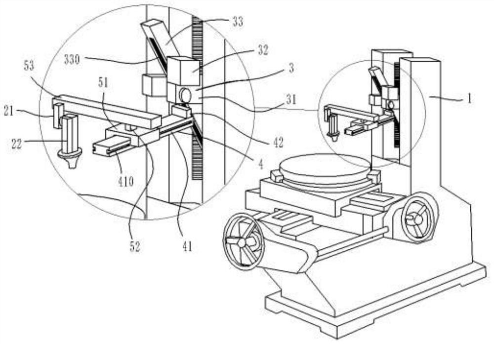
Universal oscillating processing head for machine tool
A technology of universal mechanism and machine head, which is applied in the direction of metal processing machinery parts, metal processing equipment, manufacturing tools, etc., can solve the problem that the machine tool cannot meet the multi-angle processing requirements, etc., to increase the range of rotation angle, strong practicability, The effect of simple overall structure
- Summary
- Abstract
- Description
- Claims
- Application Information
AI Technical Summary
Problems solved by technology
Method used
Image
Examples
Embodiment 1
[0024] Embodiment 1: as figure 1 , 2 The shown universal oscillating processing head for a machine tool includes a connecting structure for connecting with the machine tool, and a universal processing head 1 arranged on the connecting mechanism; the universal processing head 1 includes a universal mechanism, and The machine head 2 arranged on the universal mechanism; the universal mechanism includes a first steering mechanism 3, a second moving mechanism 4, and a third moving mechanism 5 capable of realizing three-dimensional movement;
[0025] The first steering mechanism 3 is movably arranged on the connection structure. The first steering mechanism 3 includes a U-shaped clip 31, a precision indexing table 32 installed on the U-shaped clip 31, and the precision indexing table 32 and the U-shaped clip. The first lifting base 33 that is movably connected to the piece 31; the first lifting base 33 forms an angle with the U-shaped clamp 31 through the precision indexing table 3...
Embodiment 2
[0031] Embodiment 2: Different from Embodiment 1: as image 3 , 4As shown, the elongated rail 410 adopts the LM rail; the slider base 51 adopts the LM slider; and the longitudinal extension rod 41 is provided with a lead screw motor 411, and the lead screw motor 411 is provided with a lead screw 412 passing through the LM slider , and the inside of the LM slider is provided with a sliding steel column assembly that matches the pattern of the lead screw 412, and the LM slider can move back and forth on the LM track through the sliding steel column assembly and the lead screw 412.
Embodiment 3
[0032] Embodiment 3: Different from Embodiment 1: as Figure 5 As shown, there are 2 machine heads 2, and an adjustment groove 530 is arranged on the lateral surface of the transverse extension rod 53; Each machine head 2 can move back and forth on the transverse extension rod 53, and the connecting block 21 can be fixedly connected on the transverse extension rod 53 through the adjusting bolt.
PUM
 Abstract
Description
Claims
Application Information
 - R&D
- Intellectual Property
- Life Sciences
- Materials
- Tech Scout
- Unparalleled Data Quality
- Higher Quality Content
- 60% Fewer Hallucinations
Browse by: Latest US Patents, China's latest patents, Technical Efficacy Thesaurus, Application Domain, Technology Topic, Popular Technical Reports.
© 2025 PatSnap. All rights reserved.Legal|Privacy policy|Modern Slavery Act Transparency Statement|Sitemap|About US| Contact US: help@patsnap.com


