
Top plate drilling equipment and method for installation of decoration lamps of buildings

A technology for lamp installation and architectural decoration, applied in drilling/drilling equipment, metal processing equipment, manufacturing tools, etc. The effect of improving operational safety

Inactive Publication Date: 2020-10-02
安徽省天和瑞通信息科技有限公司
View PDF0 Cites 1 Cited by
  • Summary
  • Abstract
  • Description
  • Claims
  • Application Information

AI Technical Summary

Problems solved by technology

[0007] When drilling the existing installation holes, a hand-held drilling machine is used to manually place tools such as ladders in a suitable position, and the hand-held drilling machine climbs up the ladder to drill holes on the roof. There is a certain degree of danger, and a lot of waste will be generated when drilling, which will fall directly to the ground. In addition, when workers drill holes, they need to look up at the roof to operate. The waste generated by drilling can easily enter the human eye, affecting sight and Health, to further increase the danger when drilling

Method used


Image

  • Top plate drilling equipment and method for installation of decoration lamps of buildings
  • Top plate drilling equipment and method for installation of decoration lamps of buildings
  • Top plate drilling equipment and method for installation of decoration lamps of buildings

Examples


Embodiment 1

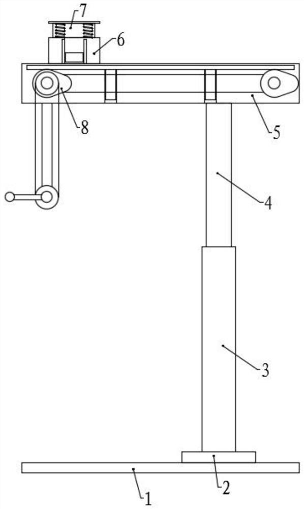
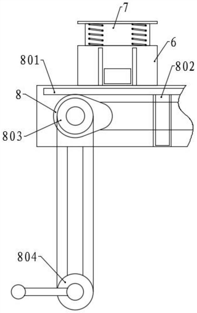
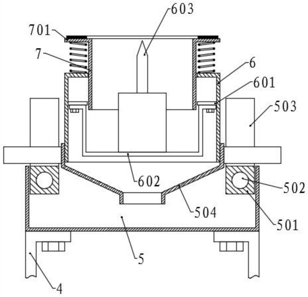
[0054] Please refer to the accompanying drawings, the present invention provides a technical solution: a roof drilling device for installing architectural decorative lamps, including a base 1, the four corners of the bottom surface of the base 1 are provided with rollers, brakes are provided on the rollers, and the top surface of the base 1 The right side is rotatably connected with a rotating seat 2, the side wall of the rotating seat 2 is fixed with a bevel gear 201, and the first bevel gear 202 is meshed with the bevel gear 201, and the first bevel gear 202 is connected with a motor, and the rotating seat 2 A lifting assembly is arranged on the top of the lifting assembly, and a fixed groove 5 is fixed on the top of the lifting assembly. The interior of the fixed groove 5 is provided with a horizontal movement assembly, and the outside is provided with a vertical movement assembly. The moving blocks are symmetrically fixed on both sides, and the moving blocks are correspondi...

Embodiment 2

[0068] The structure of this embodiment is basically the same as that of Embodiment 1, the difference is that a lower hopper 505 is fixed on the side of the bottom surface of the fixing groove 5 away from the lifting assembly, and a threaded pipe 506 is fixed on the bottom of the lower hopper 505, and the threaded pipe 506 is connected with the fixed The bottom surface of the groove 5 is fixedly connected, and the threaded pipe 506 is threadedly connected with a collecting tube, and the fixed groove 5 is rotatably connected with an inclined blanking plate 9, and the lower end of the blanking plate 9 is positioned above the blanking hopper 505. The middle bottom surface of the plate 9 and the bottom surface of the fixed groove 5 are provided with a spring, and the bottom surface of the blanking plate 9 is provided with a second cam 901 away from the side of the lower hopper 505, and the second cam 901 is fixed with a camshaft 902, and the camshaft 902 is rotatably connected with...

Embodiment 3

[0071]The structure of this embodiment is basically the same as that of Embodiment 1, the difference is that the middle of the bottom surface of the fixing groove 5 is slidably connected with the third slider 1002 along the length direction, the bottom surface of the third slider 1002 is fixed with an indicator light 1003, and the third slider 1002 is fixed on the bottom surface, and the second The third screw rod 10 is sleeved on the three sliders 1002, and the third screw rod 10 is rotationally connected with the bottom surface of the fixed groove 5, and a fifth pulley 1001 is fixed on one end, and the end surface of the fixed groove 5 corresponds to the fourth pulley 507 The position between the fifth pulley 1001 is rotationally connected with an adjustment wheel 508, and the fourth pulley 507, the fifth pulley 1001 and the adjustment wheel 508 are connected by a transmission belt, and the position of the transmission belt is adjusted by the adjustment wheel 508 so that the t...


PUM


Abstract

The invention discloses top plate drilling equipment and method for installation of decoration lamps of buildings, and belongs to the technical field of building decoration. The top plate drilling equipment comprises a base, a rotating seat and a lifting assembly. A fixing groove is fixed to the top of the lifting assembly. A collecting hopper, a transverse moving assembly and a vertical moving assembly are arranged on the fixing groove. A fixing frame and a drilling machine are fixed to the collecting hopper, and a drill bit is arranged on the drilling machine. According to the top plate drilling equipment and method, the height of the fixing groove is adjusted through the lifting assembly, the collecting hopper drives structures such as the drilling machine to move through the transversemoving assembly, and the position of the drill bit is adjusted; and the vertical moving assembly is operated on the indoor ground through a worker, the drilling machine is driven to move upwards fordrilling, the worker does not need to climb for operation through tools such as a ladder, waste generated by drilling enters the fixing groove through the collecting hopper to be collected, the problem that waste is scattered to the ground due to traditional handheld drilling is avoided, and the problems that the waste is splashed into human eyes, and accidental injuries are caused are also avoided.

Description

technical field [0001] The invention relates to the technical field of architectural decoration, in particular to a roof drilling device and a drilling method for installing architectural decorative lamps. Background technique [0002] Architecture is the general term for buildings and structures. It is an artificial environment created by people in order to meet the needs of social life, using the material and technical means they have mastered, and using certain scientific laws, Feng Shui concepts and aesthetic principles. In simple terms, architectural decoration refers to the various treatments of the internal and external surfaces and spaces of buildings with decorative materials or ornaments in order to protect the main structure of the building, improve the physical performance of the building, use the function and beautify the building. [0003] Architectural decoration is an indispensable part of people's life, and it is an important friend for human beings to taste...

Claims


Application Information

Patent Timeline
IPC IPC(8): B23B45/00B23B45/14B25F5/00
CPCB23B45/00B25F5/00B25H1/0021
Inventor 吴宪
Owner 安徽省天和瑞通信息科技有限公司
Learn More