A kind of laying hen breeding cage with protective function

A protective function and breeding cage technology, which is applied in the field of laying hen breeding cages, can solve problems such as broken eggs, and achieve the effect of reducing the possibility of broken eggs and the possibility of eggs being broken

Active Publication Date: 2021-12-14
唐山市龙凤牧业科技有限公司
View PDF3 Cites 0 Cited by
  • Summary
  • Abstract
  • Description
  • Claims
  • Application Information

AI Technical Summary

Problems solved by technology

[0004] In view of the above-mentioned related technologies, when the egg is in contact with the egg stopper at a relatively high speed during the rolling of the egg, the inventor believes that there is a defect that the egg may be broken

Method used


Image

  • A kind of laying hen breeding cage with protective function
  • A kind of laying hen breeding cage with protective function
  • A kind of laying hen breeding cage with protective function

Examples


Embodiment 1

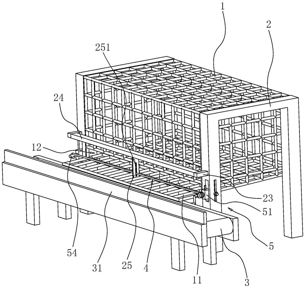
[0040] Such as figure 1As shown, the breeding cage includes a cage body 1, and a pair of sides of the cage body 1 are respectively fixedly connected with support frames 2. The bottom of the cage body 1 is provided with a bottom plate 11 with a mesh, and the bottom plate 11 is arranged obliquely.

[0041] One side of the cage body 1 is provided with an egg outlet 12 , and the egg outlet 12 is placed on the upper side of the bottom plate 11 . A conveyor belt 3 is provided near the egg outlet 12 , one side of the bottom plate 11 extends to the upper side of the conveyor belt 3 , and the side of the bottom plate 11 near the egg outlet 12 abuts against the upper surface of the conveyor belt 3 .

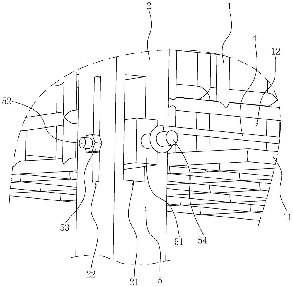
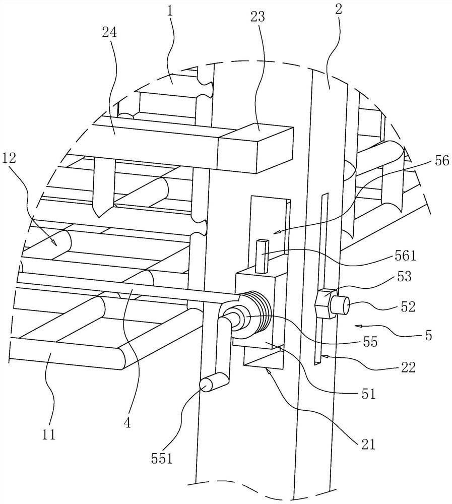
[0042] Such as figure 1 As shown, the side of the cage body 1 close to the egg outlet 12 is provided with an egg retaining rope 4, the egg retaining rope 4 is in a tensioned state, and the egg retaining rope 4 has a certain degree of elasticity. Both ends of the egg retaining rope 4 are...

Embodiment 2

[0061] Such as Figure 5 As shown, the difference between this embodiment and Implementation 1 is that a connecting plate 6 is provided between the conveyor belt 3 and the egg retaining rope 4, the connecting plate 6 is placed on the upper side of the bottom plate 11, and the lower surface of the connecting plate 6 is fixedly connected There are bristles 61, and a height adjustment mechanism 7 for fixing the connecting plate 6 is provided between the connecting plate 6 and the third support rod 24 .

[0062] The eggs leaving the egg retaining rope 4 pass through the lower side of the connecting plate 6 and fall onto the conveyor belt 3. When the eggs pass through the lower side of the connecting plate 6, the eggs are in contact with the bristles 61, and the bristles 61 play a certain buffering effect on the eggs, reducing the Possibility of being broken when small eggs fall on the conveyor belt 3.

[0063] While the bristles 61 play a buffering role on the eggs, the bristles ...


PUM


Abstract

This application relates to the field of laying hen breeding, in particular to a protective cage for laying hens, comprising a cage, the bottom of the cage is provided with an inclined bottom plate, and one side of the cage is provided with an egg outlet , the egg outlet is placed on the upper side of the bottom plate, and a conveyor belt is provided on the side close to the egg outlet. The upper surface of the conveyor belt is fixedly connected with a baffle on the side away from the egg outlet. One side of the mouth extends to the upper side of the conveyor belt and the bottom plate abuts against the upper surface of the conveyor belt, and the side near the egg outlet is provided with an egg retaining rope that contacts the rolled eggs, and the egg retaining rope is elastic and under tension. This application has the effect of reducing the possibility of eggs being broken.

Description

technical field [0001] The present application relates to the field of laying hen breeding, in particular to a protective cage for laying hens. Background technique [0002] At present, laying hens are generally raised in cages, and the eggs produced by the laying hens are collected, and the collected eggs are packaged or processed. [0003] The Chinese utility model patent with the existing authorization announcement number of CN209330896U discloses a chicken farm egg collection device, including a chicken cage, a moving wheel is arranged under the chicken cage, and a chicken manure collection tank is arranged in the chicken cage, and the chicken manure collection tank is used for collecting chicken manure. A standing board is arranged above the chicken manure collecting tank, and a mesh is arranged on the standing board. There is a feeding tank on the side of the chicken cage, a fixing plate is set on the feeding tank, a fixing hook is arranged on the top of the fixing p...

Claims


Application Information

Patent Timeline
Patent Type & Authority Patents(China)
IPC IPC(8): A01K31/00A01K31/16
CPCA01K31/002A01K31/165
Inventor 耿维力
Owner 唐山市龙凤牧业科技有限公司
Why Eureka
Try Eureka