Wall cable fixing device for mounting lamp switch

A lamp switch and fixing device technology, applied in the direction of electrical components, etc., can solve the problems of wire falling off, fire, easy damage of contacts, etc., to achieve the effect of convenient arrangement and discharge, and improved heat dissipation effect

Inactive Publication Date: 2020-09-29
汉思科技集团股份有限公司
View PDF0 Cites 0 Cited by
  • Summary
  • Abstract
  • Description
  • Claims
  • Application Information

AI Technical Summary

Problems solved by technology

[0003] There are too many wires connected to the switch socket, and because it is impossible to effectively clamp, fix and arrange a single cable, it is easy to cause the cables to be discharged in disorder in the installation groove of the switch socket or even to be wound together in disorder, resulting in poor heat dissipation. When a fire occurs, and the switch socket wires are connected to more functional panels and installed back on the wall bottom box, it needs to be pressed with a lot of pressure to install and position, which will easily cause two hidden dangers. One is that the installed contacts are easily damaged, especially The installation positioning parts, terminal blocks, etc. on the wall bottom box; the second is that when the installation and positioning are pressed down forcefully, due to the physical characteristics of the wire elasticity and hardness, the contact stress between the wire and the terminal block is redistributed, which may easily cause poor contact between the wire and the terminal block , and even cause failures such as wire falling off

Method used


Image

  • Wall cable fixing device for mounting lamp switch
  • Wall cable fixing device for mounting lamp switch
  • Wall cable fixing device for mounting lamp switch

Examples


Embodiment Construction

[0033] The following will clearly and completely describe the technical solutions in the embodiments of the present invention with reference to the accompanying drawings in the embodiments of the present invention. Obviously, the described embodiments are only some, not all, embodiments of the present invention. Based on the embodiments of the present invention, all other embodiments obtained by persons of ordinary skill in the art without creative efforts fall within the protection scope of the present invention.

[0034] In describing the present invention, it is to be understood that the terms "opening", "upper", "lower", "thickness", "top", "middle", "length", "inner", "surrounding" etc. Indicating orientation or positional relationship is only for the convenience of describing the present invention and simplifying the description, and does not indicate or imply that the components or elements referred to must have a specific orientation, be constructed and operated in a sp...


PUM


Abstract

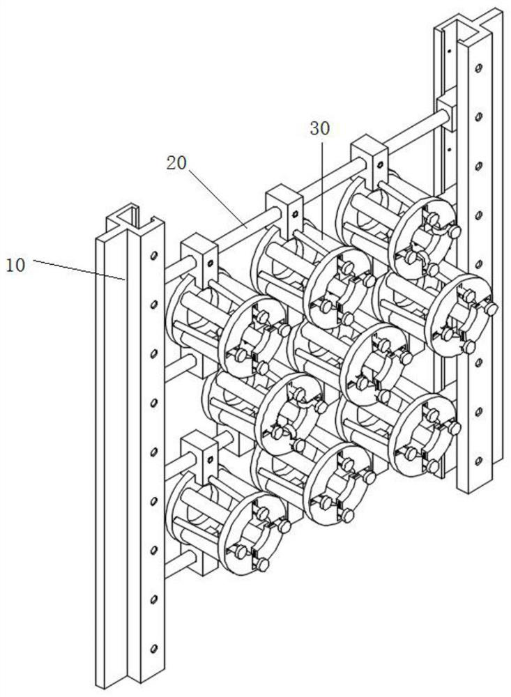
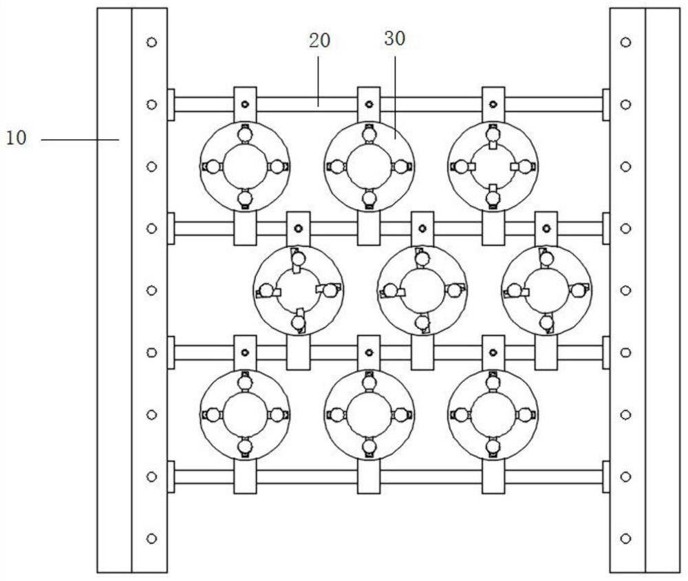
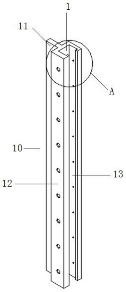
The invention discloses a wall cable fixing device for mounting a lamp switch, and relates to the technical field of cable mounting and fixing. The device comprises groove plates located on the two sides, a plurality of supporting rods are arranged on the two groove plates, and the supporting rods are parallel to one another and are arranged at equal intervals; a cable clamping mechanism is arranged between any two adjacent supporting rods; the cable clamping mechanism comprises a fixing ring, and a first fixing block and a second fixing block which are movably matched with the supporting rodare arranged on the two sides of the fixing ring respectively. Four extrusion rods and four elastic contraction devices are arranged on one surface of the fixing ring, and the four extrusion rods areclose to one side of the central axis of the fixing ring; a movable ring is arranged at the ends of the four elastic contraction devices, an open groove matched with the extrusion rod is formed in theinner side of the movable ring, and an extrusion block is arranged in the open groove in a matched mode. Through the combined use of the groove plate, the supporting rod and the cable clamping mechanism, the incoming lines of the switch socket can be conveniently arranged and arranged, and the heat dissipation effect in the switch socket mounting groove is improved.

Description

technical field [0001] The invention belongs to the technical field of cable installation and fixing, and in particular relates to a wall cable fixing device for installing lamp switches. Background technique [0002] The traditional switch socket is provided with a plurality of terminal blocks on the back of the functional panel of the switch socket. The signal wires are collectively referred to as wires), plugged into the jacks of the above-mentioned terminal blocks, the screws are tightened, and then the functional panel is pressed down and installed on the wall bottom box. Generally, a five-hole socket needs to be connected to 3 wires, a five-hole switch socket needs to be connected to 5 wires, and a multi-switch socket needs to be connected to more wires. [0003] There are too many wires connected to the switch socket, and because it is impossible to effectively clamp, fix and arrange a single cable, it is easy to cause the cables to be discharged in disorder in the i...

Claims


Application Information

Patent Timeline
Patent Type & Authority Applications(China)
IPC IPC(8): H02G3/04H02G3/36H02G3/03
CPCH02G3/03H02G3/0431H02G3/36
Inventor 何庆亮
Owner 汉思科技集团股份有限公司
Why Eureka
Try Eureka