
Automatic electrical cabinet

A technology for electrical cabinets and rotating shafts, which is applied to electrical components, substation/power distribution device shells, substation/switch layout details, etc., and can solve problems affecting internal electrical components, short circuits of electronic components inside control cabinets, and no universal wheels, etc. question

Inactive Publication Date: 2020-09-29
胡晓霖
View PDF5 Cites 7 Cited by
  • Summary
  • Abstract
  • Description
  • Claims
  • Application Information

AI Technical Summary

Problems solved by technology

Existing automatic control equipment is in use, due to the entry of external air, it is easy to bring in some dust, but most of the existing control cabinets are not able to automatically control the dust content inside the control cabinet. If it is conductive, it will easily cause a short circuit of the electronic components inside the control cabinet, which will easily lead to a fire. If the staff cannot find out in time, it will have a huge impact
[0003] Automated electrical cabinets will be transferred according to different usage environments. At present, most of the existing automated electrical cabinets are not designed with universal wheels for movement. They will also shake during the process of moving or moving, which will directly affect the internal electrical components. , which in turn affects the damage of electrical components in the automated electrical cabinet and reduces the service life of the electrical cabinet. Therefore, the present invention provides an automated electrical cabinet

Method used


Image

  • Automatic electrical cabinet
  • Automatic electrical cabinet
  • Automatic electrical cabinet

Examples


Embodiment Construction

[0028] In order to make the object, technical solution and advantages of the present invention clearer, the present invention will be further described in detail below in conjunction with the accompanying drawings and embodiments. It should be understood that the specific embodiments described here are only used to explain the present invention, not to limit the present invention.

[0029] The components of the embodiments of the invention generally described and shown in the figures herein may be arranged and designed in a variety of different configurations. Accordingly, the following detailed description of the embodiments of the invention provided in the accompanying drawings is not intended to limit the scope of the claimed invention, but merely represents selected embodiments of the invention.

[0030] Based on the embodiments of the present invention, all other embodiments obtained by persons of ordinary skill in the art without making creative efforts belong to the pro...


PUM


Abstract

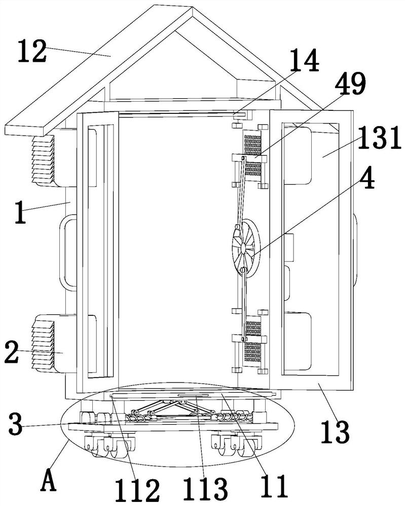
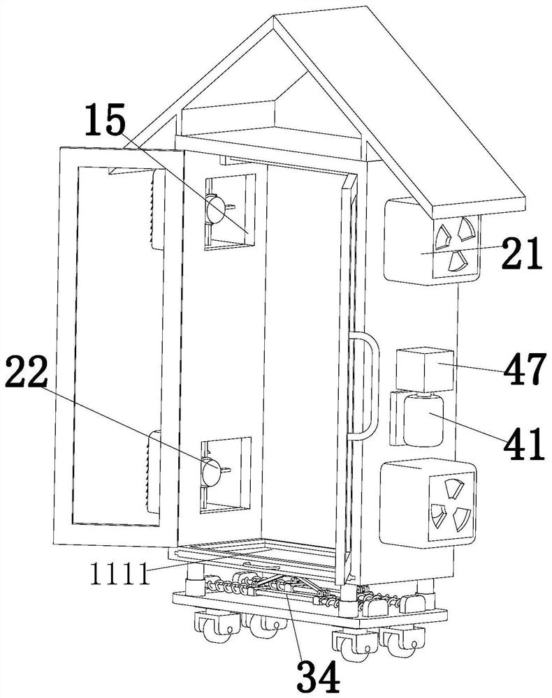
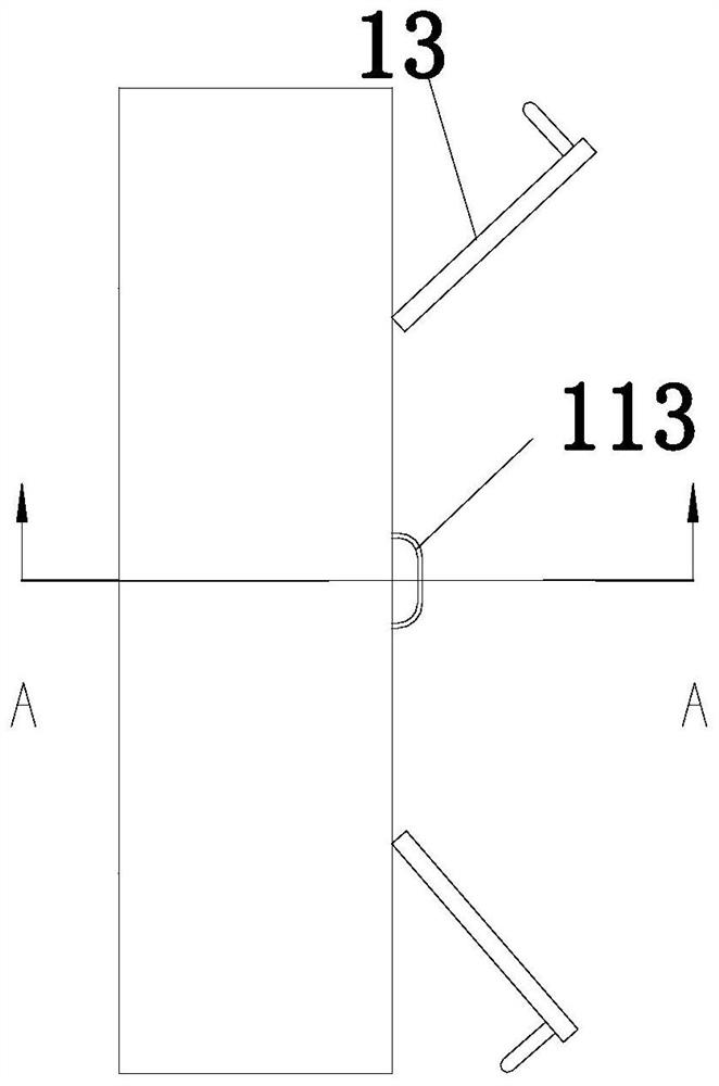
The invention relates to the technical field of electrical equipment. The invention particularly relates to an electrical cabinet. The electrical cabinet comprises an electrical cabinet body, heat dissipation assemblies, a damping assembly and a dust removal assembly. The number of the heat dissipation assemblies is two. The two groups of heat dissipation assemblies are fixedly arranged on the twosides of the electrical cabinet body respectively; the dust removal assembly is fixedly arranged on one side in the electrical cabinet body; the damping assembly is fixedly arranged below the electrical cabinet body. According to the invention, the heat dissipation assemblies, the damping assembly and the dust removal assembly are arranged; the damping assembly can achieve damping and anti-bumping effects on the electrical cabinet; the situation that electrical elements in the electrical cabinet are damaged due to the fact that the center of gravity of the electrical cabinet is unstable in the moving process or vibration is generated when the electrical cabinet encounters an uneven road surface in the moving process is avoided, the heat dissipation assemblies can conduct heat dissipationtreatment on the electrical cabinet, and the dust removal part can remove dust on a filter screen.

Description

technical field [0001] The invention relates to the technical field of electrical equipment, in particular to an automated electrical cabinet. Background technique [0002] At present, with the development of science and technology, there are more and more applications of automatic control appliances on equipment. Therefore, the electrical automation control cabinet came into being. The electrical control cabinet is to assemble switchgear, measuring instruments, protective appliances and auxiliary equipment in a metal cabinet according to the requirements of electrical wiring. Existing automatic control equipment is in use, due to the entry of external air, it is easy to bring in some dust, but most of the existing control cabinets are not able to automatically control the dust content inside the control cabinet. If it is conductive, it will easily cause a short circuit of the electronic components inside the control cabinet, which will easily lead to a fire. If the staff ...

Claims


Application Information

Patent Timeline
Patent Type & Authority Applications(China)
IPC IPC(8): H02B1/56H02B1/54H02B1/28
CPCH02B1/28H02B1/54H02B1/565
Inventor 胡晓霖
Owner 胡晓霖
Learn More