
Movable bottom seat of energy-saving vortex air compressor and mounting method thereof

A mobile base and air compressor technology, applied in the direction of mobile frames, engine frames, machines/engines, etc., can solve problems such as inconvenient installation, unable to install air compressors, and unable to reduce damage to scroll air compressors, etc. To achieve the effect of easy installation and adjustment

Inactive Publication Date: 2020-02-21
徐州康翔精密制造有限公司
View PDF6 Cites 9 Cited by
  • Summary
  • Abstract
  • Description
  • Claims
  • Application Information

AI Technical Summary

Problems solved by technology

[0003] The mobile base of the traditional scroll air compressor cannot be effectively adjusted, and it is not easy to install. It cannot be installed according to different types and specifications of air compressors. During use, the vibration generated by the work cannot be offset and removed, and shock absorption cannot be achieved. , cannot reduce the damage caused by vibration to the scroll air compressor

Method used


Image

  • Movable bottom seat of energy-saving vortex air compressor and mounting method thereof
  • Movable bottom seat of energy-saving vortex air compressor and mounting method thereof
  • Movable bottom seat of energy-saving vortex air compressor and mounting method thereof

Examples


Embodiment

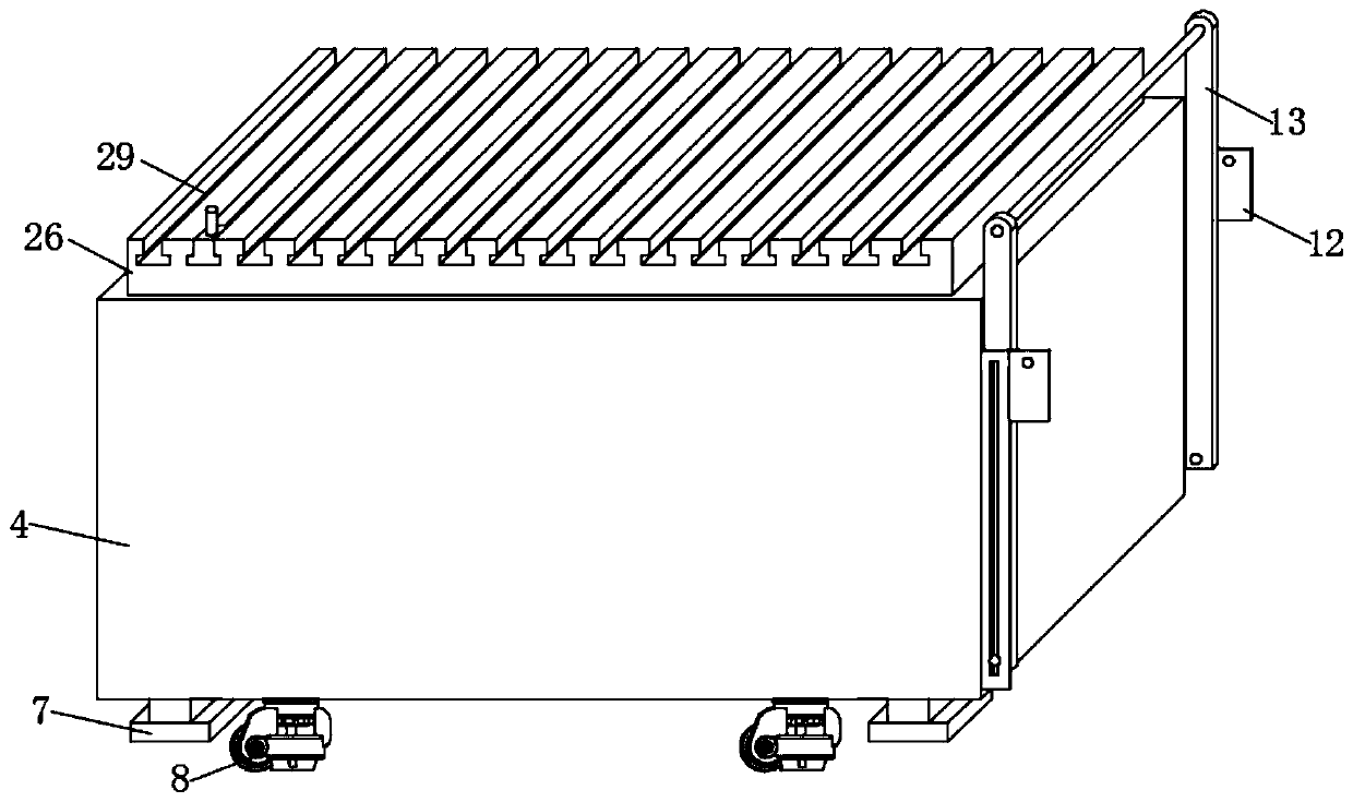
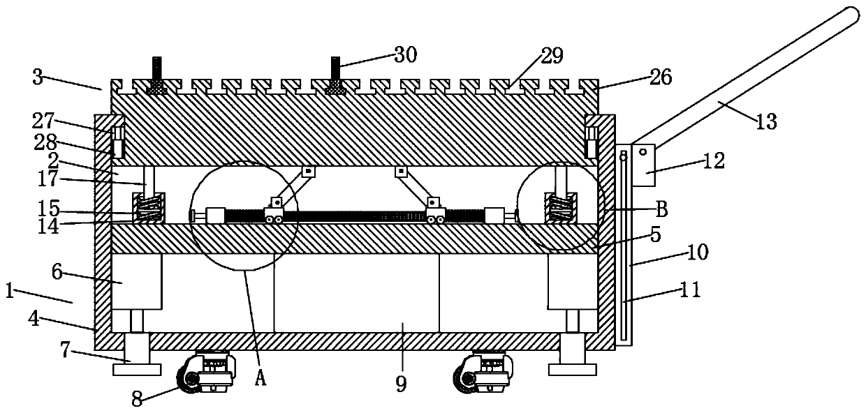
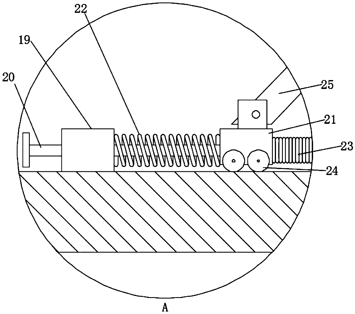
[0025] A mobile base of an energy-saving scroll air compressor, comprising a supporting mechanism 1, a shock absorbing mechanism 2 and a mounting mechanism 3, the top of the supporting mechanism 1 is equipped with a shock absorbing mechanism 2, and the top of the shock absorbing mechanism 2 is installed with The installation mechanism 3, the support mechanism 1 includes a support box 4, a fixed partition 5, a support hydraulic cylinder 6, a support foot plate 7, a self-locking wheel 8, a hydraulic station 9, an adjustment plate 10, an adjustment chute 11, and a limit plate 12 and handrails 13, the inside of the support box 4 is fixedly equipped with a fixed partition 5, and the four corners of the bottom of the fixed partition 5 are fixedly installed with a support hydraulic cylinder 6, and the output end of the support hydraulic cylinder 6 is connected from The bottom of the supporting box body 4 passes through, and the output ends of the supporting hydraulic cylinders 6 are a...


PUM


Abstract

The invention discloses a movable bottom seat of an energy-saving vortex air compressor and a mounting method thereof. The movable bottom seat of the energy-saving vortex air compressor comprises a supporting mechanism, a damping mechanism and a mounting mechanism, wherein the damping mechanism is mounted at the top of the supporting mechanism, and the mounting mechanism is mounted at the top of the damping mechanism. In specific use of the movable bottom seat of the energy-saving vortex air compressor, a mounting column is enabled to slide in suitable adjustment sliding chutes due to the factthat the position of the mounting column can be adjusted according to the size and the mounting position of the air compressor bottom seat, then a screw at the top of the mounting column is enabled to pass through a mounting hole of the air compressor, then the air compressor is fixed through the bolt, and mounting can be performed according to the air compressors different in type and specification, and when the air compressors work, vibration is transmitted through the corresponding adjustment sliding chutes, a transmission strut pushes a buffering sliding block to slide towards two sides when the transmission strut is subject to vibration impact, the buffering sliding block compresses a third damping spring when the buffering sliding block slides towards the two sides, a compression spring is stretched when the buffering sliding block compresses the third damping spring, and accordingly impact generated due to vibration is counteracted, and accordingly damping is realized.

Description

technical field [0001] The invention belongs to the technical field of air compressors, in particular to a mobile base of an energy-saving scroll air compressor and an installation method thereof. Background technique [0002] The scroll air compressor needs to be moved and installed through the mobile base during use to ensure the stable working performance of the scroll air compressor and increase its flexibility in use; [0003] The mobile base of the traditional scroll air compressor cannot be effectively adjusted, and it is not easy to install. It cannot be installed according to different types and specifications of air compressors. During use, the vibration generated by the work cannot be offset and removed, and shock absorption cannot be achieved. , It is impossible to reduce the damage caused by vibration to the scroll air compressor. Invention content: [0004] The object of the present invention is to provide a mobile base of an energy-saving scroll air compres...

Claims


Application Information

Patent Timeline
IPC IPC(8): F16F15/023F16F15/04F16M3/00F16M7/00F04C29/00
CPCF04C29/00F16F15/023F16F15/04F16M3/00F16M7/00
Inventor 吴文超
Owner 徐州康翔精密制造有限公司
Learn More