


Quick Research
Generate reliable direction feasibility study reports for your R&D in just a few steps.

Technical Q&A
Discover and master advanced knowledge NOW. Basics, ideas, possibilities, all at once.

Find Solutions
As an expert in R&D theories, this can generate solutions to your technical problems instantly.

Evaluate Feasibility
Analyze your overall solution with one click, know your potential R&D risks in advance.

Monitor Landscape
Get weekly tech updates, stay abreast of the latest tech innovations and key insights.
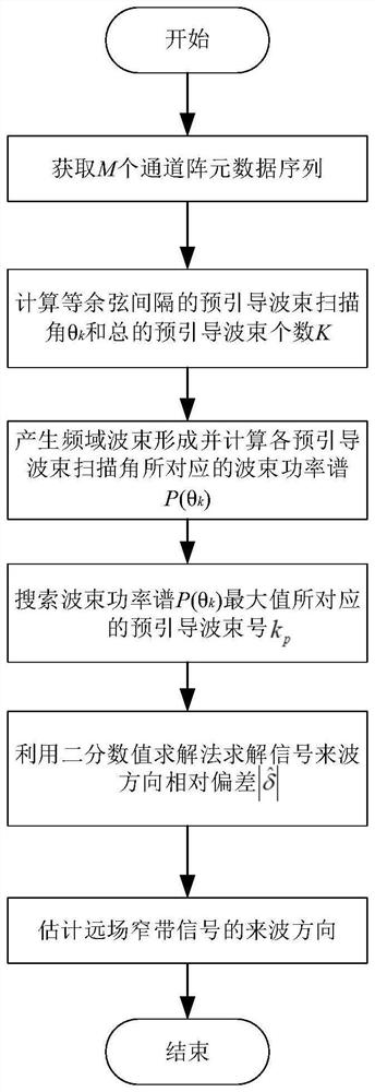
A method for estimating the direction of arrival of far-field narrowband signals based on numerical solution of directivity model
A narrow-band signal and numerical solution technology, which is applied in the field of signal processing, can solve problems such as the decrease in the accuracy of direction of arrival estimation, and achieve strong robustness and good estimation performance.
- Summary
- Abstract
- Description
- Claims
- Application Information
AI Technical Summary
Problems solved by technology
Method used
Image

Examples
Embodiment 1
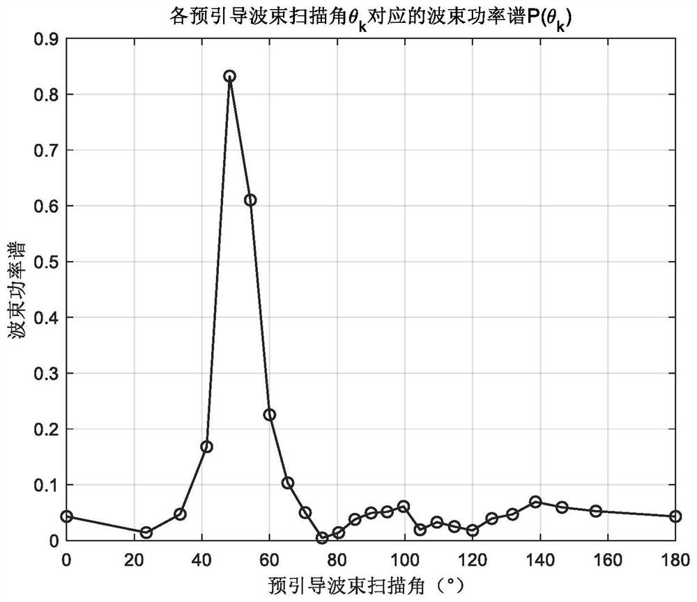
[0122] The simulation signal parameters are respectively set as: signal amplitude A=1, initial phase The pulse width of the far-field narrowband signal is 1s, the length of the received signal is 1.032s, the number of sampling points is N=4096, the total number of array elements is M=21, and the frequency of the far-field narrowband signal is f 0 =1250Hz, sampling frequency f s =4000Hz, the distance between adjacent array elements is d=0.6m, the propagation speed of the far-field narrowband signal in the medium is c=1500m / s (the propagation speed of sound in water), and the direction of arrival of the signal is θ T =50.7035°, SNR=-6dB.
[0123] Firstly, according to the given array parameters, the total number of pre-steering beams K=25 is automatically generated, from which we can obtain the scanning angle θ of the pre-steering beams k ,即[0 23.5565 33.5573 41.4096 48.1897 54.3147 60.000065.3757 70.5288 75.5225 80.4059 85.2198 90.0000 94.7802 99.5941 104.4775109.4712 114.62...
Embodiment 2
[0134] The simulation signal parameters are respectively set as: signal amplitude A=1, initial phase The pulse width length of the far-field narrowband signal is 1s, the length of the received signal is 1.032s, the number of sampling points is N=4096, the total number of array elements is M=15, and the frequency of the far-field narrowband signal is f 0 =1250Hz, sampling frequency f s =4000Hz, the distance between adjacent array elements is d=0.6m, the propagation speed of the far-field narrowband signal in the medium is c=1500m / s (the propagation speed of sound in water), and the direction of arrival of the signal is θ T =115.0576°, SNR=-6dB.
[0135] First, the total number of pre-guided beams K=18 is automatically generated according to the given array parameters, from which we can obtain the pre-guided beam scanning angle θ k , That is, [0 28.0725 40192 49.6798 58.0343 65.6843 72.895479.8358 86.6277 93.3723 100.1642 107.104.3157 121.9657 130.8808151.9275 180.0000] °.
...
PUM
 Abstract
Description
Claims
Application Information
 - R&D Engineer
- R&D Manager
- IP Professional
- Industry Leading Data Capabilities
- Powerful AI technology
- Patent DNA Extraction
Browse by: Latest US Patents, China's latest patents, Technical Efficacy Thesaurus, Application Domain, Technology Topic, Popular Technical Reports.
© 2024 PatSnap. All rights reserved.Legal|Privacy policy|Modern Slavery Act Transparency Statement|Sitemap|About US| Contact US: help@patsnap.com