Far-field narrow-band signal incoming wave direction estimation method based on directivity model numerical solution

A technology of narrow-band signal and direction of arrival, applied in the field of signal processing, can solve problems such as the decrease in accuracy of direction of arrival estimation

Active Publication Date: 2020-09-29
SOUTHEAST UNIV
View PDF5 Cites 0 Cited by
  • Summary
  • Abstract
  • Description
  • Claims
  • Application Information

AI Technical Summary

Problems solved by technology

However, for some directions of arrival, the main lobe of the angular spectrum does not mat

Method used


Image

  • Far-field narrow-band signal incoming wave direction estimation method based on directivity model numerical solution
  • Far-field narrow-band signal incoming wave direction estimation method based on directivity model numerical solution
  • Far-field narrow-band signal incoming wave direction estimation method based on directivity model numerical solution

Examples


Embodiment 1

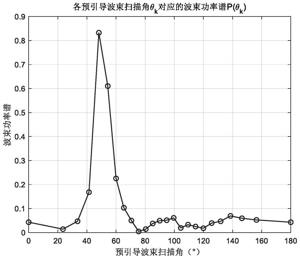
[0122] The simulation signal parameters are set as follows: signal amplitude A=1, initial phase The pulse width of the far-field narrowband signal is 1s, the length of the received signal is 1.032s, the number of sampling points is N=4096, the total number of array elements is M=21, and the frequency of the far-field narrowband signal is f 0 =1250Hz, sampling frequency f s = 4000Hz, the distance between adjacent array elements d = 0.6m, the propagation velocity of far-field narrowband signal in the medium c = 1500m / s (the propagation velocity of sound in water), the signal incoming wave direction θ T =50.7035°, SNR=-6dB.

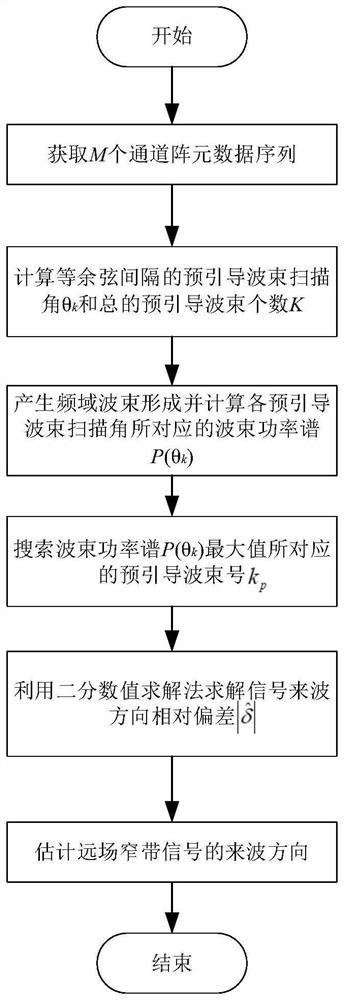
[0123] First, the total number of pre-guided beams K=25 is automatically generated according to the given array parameters, from which we can obtain the pre-guided beam scanning angle θ k ,即[0 23.5565 33.5573 41.4096 48.1897 54.3147 60.000065.3757 70.5288 75.5225 80.4059 85.2198 90.0000 94.7802 99.5941 104.4775109.4712 114.6243 120.0000 125.6853 131.8103 ...

Embodiment 2

[0134] The simulation signal parameters are set as follows: signal amplitude A=1, initial phase The pulse width of the far-field narrowband signal is 1s, the length of the received signal is 1.032s, the number of sampling points is N=4096, the total number of array elements is M=15, and the frequency of the far-field narrowband signal is f 0 =1250Hz, sampling frequency f s = 4000Hz, the distance between adjacent array elements d = 0.6m, the propagation velocity of far-field narrowband signal in the medium c = 1500m / s (the propagation velocity of sound in water), the signal incoming wave direction θ T =115.0576°, SNR=-6dB.

[0135] First, the total number of pre-guided beams K=18 is automatically generated according to the given array parameters, from which we can obtain the pre-guided beam scanning angle θ k , That is, [0 28.0725 40192 49.6798 58.0343 65.6843 72.895479.8358 86.6277 93.3723 100.1642 107.104.3157 121.9657 130.8808151.9275 180.0000] °.

[0136] Then for the k...


PUM


Abstract

The invention discloses a far-field narrow-band signal incoming wave direction estimation method based on directivity model numerical solution, and the method comprises the steps: 1, obtaining M-channel array element data x1 (n), x2 (n),..., xM (n); 2, automatically generating pre-guided beam scanning angles theta k at equal cosine intervals and the total number K of pre-guided beams according togiven array parameters; 3, performing frequency domain beam forming on the far-field narrow-band signal with the known frequency f0, and solving a beam power spectrum P (theta k) corresponding to eachpre-guided beam scanning angle of the far-field narrow-band signal with the known frequency; 4, searching a pre-guided beam number kp corresponding to the maximum value of the beam power spectrum P (theta k); 5, solving the relative deviation of the incoming wave direction of the signal by using a binary numerical solution method; and 6, estimating the incoming wave direction of the far-field narrow-band signal. The algorithm is based on conventional beam forming, is easy to implement, small in operand and high in estimation precision, and is suitable for real-time engineering application occasions.

Description

technical field [0001] The invention belongs to the field of signal processing, in particular to a method for estimating the direction of arrival of a far-field narrowband signal based on the numerical solution of a directivity model. Background technique [0002] Target direction of arrival estimation is a basic problem in array signal processing applications such as radar, sonar, acoustics, voice and wireless communication, especially in underwater acoustic and electronic reconnaissance processing, which plays an extremely important role. In addition, in modern mobile communication systems, direction of arrival estimation has an important application in improving wireless system performance. [0003] At present, scholars at home and abroad have proposed many target direction-of-arrival estimation methods, such as minimum-variance distortion-free response, and eigenvector-based direction-of-arrival estimation algorithms (such as MUSIC, Root-MUSIC, RV-Root-MUSIC). These alg...

Claims


Application Information

Patent Timeline
IPC IPC(8): G01S3/14G01S3/78G01S3/80
CPCG01S3/143G01S3/78G01S3/80Y02D30/70
Inventor 姚帅蒋宇轩刘昱含方世良
Owner SOUTHEAST UNIV
Why Eureka
Try Eureka