Optical fiber monitoring device for debris flow

A monitoring device, debris flow technology, applied in the direction of measuring device, optical device, measuring force, etc., can solve the problems of difficult remote online monitoring, large error of solid source, high price, etc.

Inactive Publication Date: 2020-09-29
成都伊莱特光测科技有限公司
View PDF6 Cites 4 Cited by
  • Summary
  • Abstract
  • Description
  • Claims
  • Application Information

AI Technical Summary

Problems solved by technology

[0004] At present, most slope safety monitoring adopts traditional electromagnetic sensing equipment and InSAR technology. Electrical equipment does not have the ability to resist harsh environmental interference and electromagnetic interference, and it is difficult to realize remote online monitoring; InSAR technology is a newly developed space. Earth observation technology has a wide measurement range and high measurement accuracy. However, due to the influence of vegetation coverage, the solid source error in the observation value is large, the real-time performance is not strong, and the price is expensive. Therefore, we propose a debris flow optical fiber monitoring The device is used to solve the above problems

Method used


Image

  • Optical fiber monitoring device for debris flow
  • Optical fiber monitoring device for debris flow
  • Optical fiber monitoring device for debris flow

Examples


Embodiment Construction

[0032] The following will clearly and completely describe the technical solutions in the embodiments of the present invention with reference to the accompanying drawings in the embodiments of the present invention. Obviously, the described embodiments are only some, not all, embodiments of the present invention.

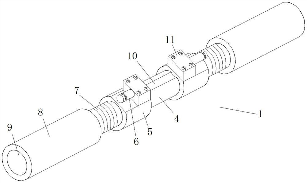
[0033] refer to Figure 1-12 , a fiber optic monitoring device for debris flow, comprising a fiber grating bolt gauge 1, a fiber grating tension sensor 2 and a fiber grating vibration sensor 3, the fiber grating bolt gauge 1 includes a strain measuring body 4, and both ends of the strain measuring body 4 are fixedly connected There is a pigtail outlet protector 5, and one end of the two pigtail outlet protectors 5 away from each other is fixedly connected with a threaded rod 7, the outer thread of the threaded rod 7 is sleeved with a sleeve 8, and the top side of the strain measuring body 4 is provided with a The fiber grating fixing groove 10, the top side of the pi...


PUM

PropertyMeasurementUnit
pore sizeaaaaaaaaaa
pore sizeaaaaaaaaaa
thicknessaaaaaaaaaa

Abstract

The invention belongs to the technical field of geological monitoring, and particularly relates to an optical fiber monitoring device for debris flow. The device comprises a fiber bragg grating anchorrod meter, a fiber bragg grating tension sensor and a fiber bragg grating vibration sensor; the fiber bragg grating anchor rod meter comprises a strain measuring body; the two ends of the strain measurement body are fixedly connected with tail fiber outgoing line protectors; threaded rods are fixedly connected with the ends, away from each other, of the two tail fiber outgoing line protectors; the outer side of each threaded rod is sleeved with a sleeve in a threaded mode; a fiber bragg grating fixing groove is formed in the top side of the strain measurement body; a fixing shell is fixedly connected with the top side of each tail fiber outgoing line protector; an optical cable fixator is detachably installed on the inner side of each fixing shell; and the fiber bragg grating tension sensor comprises an elastic structure conversion body. The optical fiber monitoring device for debris flow is reasonable in design; a traditional optical fiber grating anchor rod force measuring method isimproved; an optical fiber grating anchor rod dynamometer and an optical fiber grating displacement sensor which are used for slope sliding monitoring are improved; and the debris flow optical fibermonitoring device suitable for the field environment is researched and designed.

Description

technical field [0001] The invention relates to the technical field of geological monitoring, in particular to a debris flow optical fiber monitoring device. Background technique [0002] With the rapid development of my country's national economy, the country's infrastructure construction is rapid, and my country's long-term engineering technology development has focused on construction and neglected maintenance, and is limited by the existing engineering monitoring technology level and follow-up investment funds. , leading to the relative lack of safety monitoring and maintenance of major projects such as rivers, bridges, tunnels, slopes, and high-rise buildings. In most cases, structural health monitoring is only considered after the project is in danger or a disaster has occurred. my country is a country with large mountains and hills. The geological and natural disasters that occur every year are mainly concentrated in mountainous areas, and landslides, rockfalls and mud...

Claims


Application Information

Patent Timeline
Patent Type & Authority Applications(China)
IPC IPC(8): G01B11/16G01B11/02G01L1/24G01H9/00
CPCG01B11/02G01B11/16G01H9/004G01L1/242
Inventor 龙增辉郑志国
Owner 成都伊莱特光测科技有限公司
Why Eureka
Try Eureka