Definite time protection method and device

A protection device and definite time technology, which is applied to emergency protection circuit devices, emergency protection devices with automatic disconnection, parts of emergency protection devices, etc., can solve the problem of large error in definite time limit action time, and achieve the effect of accurate calculation

Active Publication Date: 2021-11-23
CHANGSHU SWITCHGEAR MFG CO LTD (FORMER CHANGSHU SWITCHGEAR PLANT)
View PDF5 Cites 0 Cited by
  • Summary
  • Abstract
  • Description
  • Claims
  • Application Information

AI Technical Summary

Problems solved by technology

In fact, there is a certain time difference t1 between the judgment of the sampling value I1 of the fault current and the judgment of the effective value I' of the fault current. It takes a period of time t n (such as figure 1 shown), due to the existence of t1 and t n, the definite time action time error is relatively large

Method used


Image

  • Definite time protection method and device
  • Definite time protection method and device
  • Definite time protection method and device

Examples


Embodiment Construction

[0035] A circuit breaker consists of a contact system, an operating mechanism, a tripping device (flux) and a controller. The working process of the circuit breaker is that when the main circuit current exceeds the set value, the controller sends out a tripping signal, which controls the tripping device (magnetic flux), and the tripping device (magnetic flux) triggers the action of the operating mechanism to disconnect the contacts , break the main circuit current, and the circuit breaker action is completed.

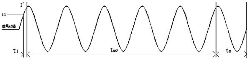
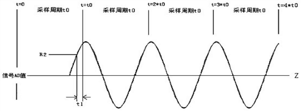
[0036] At present, the common circuit breaker over-current definite-time action method is to calculate the current effective value I' within the period according to the AD value obtained by AD sampling every period of time. At time tm0, a trip command is issued to trip the circuit breaker. In actual work, there is a certain time difference t1 between the judgment of the sampling value I1 of the fault current and the judgment of the effective value I' of the fault curre...


PUM


Abstract

The invention discloses a definite time protection method. The AD sampling is performed on an external signal to obtain the AD sampling value of the signal, and the effective value of the signal is calculated according to the AD sampling value of the signal. Any AD sampling value in a sampling period exceeds the normal range of the sampling value, and After the one sampling period, the effective value of the signal for n consecutive sampling periods exceeds the preset action signal setting value, and the sum of the consecutive n+1 sampling periods t≥tm‑t0, then the delay (t0‑t1) + After (t0-tn) time, a protection action command is issued; wherein, tm is the preset action time setting value, t0 is the sampling period of AD sampling, and tn is the preset value, which is the time from the protection action command is issued to the completion of the protection action. t1 is the time from the first sampling point when the AD sampling value exceeds the normal range of the sampling value in the one sampling period to the end of the sampling period, and the normal range of the sampling value is calculated from the setting value of the action signal. The invention also discloses a definite time protection device. Compared with the prior art, the present invention can effectively improve the time precision of the definite time action.

Description

technical field [0001] The invention relates to a definite time limit protection method and device, belonging to the technical field of switching appliances. Background technique [0002] With the development of smart grids, the importance of low-voltage circuit breakers is becoming more and more obvious. As the core component of circuit breakers, the functions of intelligent controllers are also becoming more and more perfect, from traditional three-stage protection plus grounding protection to voltage and power protection. , and then to the following directional protection, synchronous function, etc., the requirements for the controller are more and more stringent. However, for low-voltage circuit breakers, overcurrent protection is still the most important function, and people have higher and higher requirements for the accuracy of overcurrent delay and definite time limit action time. [0003] At present, the common overcurrent definite time limit action method is to ca...

Claims


Application Information

Patent Timeline
Patent Type & Authority Patents(China)
IPC IPC(8): H02H3/027H02H3/093H02H1/00H02H7/22
CPCH02H1/0007H02H3/027H02H3/0935H02H7/222
Inventor 殷建强褚东任灵
Owner CHANGSHU SWITCHGEAR MFG CO LTD (FORMER CHANGSHU SWITCHGEAR PLANT)
Why Eureka
Try Eureka