
Multifunctional terminal machine

A multi-functional terminal and integrated technology, applied in the direction of electrical components, circuits, connections, etc., can solve the problems of increasing land cost, easy to produce errors, and low work efficiency, so as to improve work efficiency, reduce working time, and save land occupation resource effect

Active Publication Date: 2020-09-25
HANGZHOU HOUYU TECH CO LTD
View PDF4 Cites 2 Cited by
  • Summary
  • Abstract
  • Description
  • Claims
  • Application Information

AI Technical Summary

Problems solved by technology

[0002] The traditional terminal punching method uses manual cutting terminal material tools, the work efficiency is low and the quality of the punching terminal cannot be guaranteed
At present, there are also some terminal punching machines on the market, but they are all single-thread processing, the work efficiency is low, and the thread head is moved many times during the movement process, which is prone to errors during the work process, resulting in the overall length of subsequent products being shorter than the theoretical value. When the situation occurs, the machines on the market are generally larger in the production process and need to occupy a larger area for placement. Excessively large occupied areas will inevitably increase the cost of land use, and a certain amount of safety must be reserved between machines. distance, resulting in an excessively large footprint for the overall equipment

Method used


Image

  • Multifunctional terminal machine
  • Multifunctional terminal machine
  • Multifunctional terminal machine

Examples


Embodiment Construction

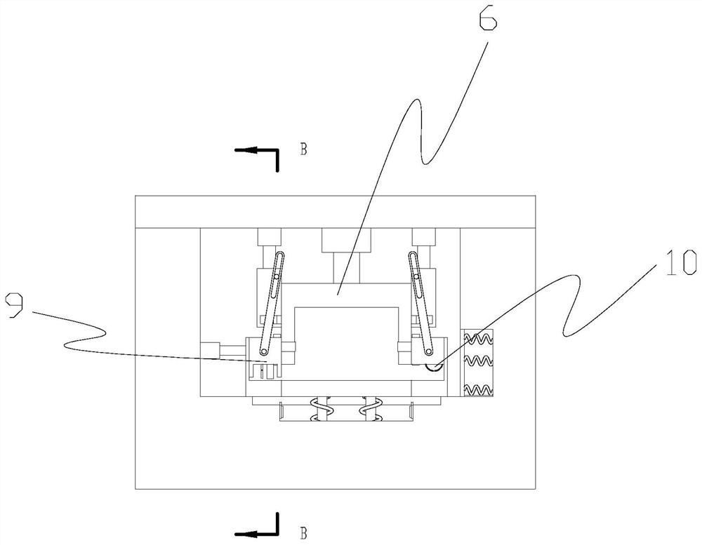
[0025] Such as Figure 1-11 As shown, a multifunctional terminal machine includes a box body 1, a cover body 2, a wire inlet 3, a discharge port 4, and an integrated terminal device 5; the box body 1 is set on the ground, and the cover body 2 is set on the ground. Above the housing, the wire inlet 3 is set on the box body, the discharge port 4 is opened on the box body, and there are multiple sets of integrated end-typing devices 5, which are evenly arranged inside the box body. Arranged in the form of strips, which effectively reduces the occupied space. Here, only two groups are set for the convenience of expression, which can be added according to requirements; the integrated end-typing device 5 includes a lifting plate 51, a guide hole 52, and a guide post 53 , the first elastic member 54, the fixing structure 6, the end structure 7, the peeling assembly 8; the lifting plate 51 is located in the box body, the guide hole 52 is opened at the bottom of the box body, and the g...


PUM


Abstract

The invention discloses a multifunctional terminal machine, which comprises a box body arranged on the ground, a cover body arranged above the shell, a wire inlet formed in the box body, a material outlet formed in the box body, and a plurality of groups of integrated terminal crimping devices arranged in the box body. The integrated terminal crimping device comprises a lifting plate arranged in the box body, a guide hole formed in the bottom of the box body, a guide column connected to the bottom of the lifting plate, a first elastic piece used for resetting the lifting plate, a fixing structure arranged above the lifting plate, terminal crimping structures arranged on the two sides of the lifting plate, and a peeling assembly arranged below the terminal crimping structures. And the guidecolumns can move back and forth in the guide holes. Through the arrangement of the lifting plate, the peeling process and the terminal crimping process are effectively combined, the working time is greatly shortened, meanwhile, errors existing in the secondary positioning process in the machining process are reduced, the product quality is effectively controlled, the occupied area is small, occupied resources are effectively saved, and the working efficiency is improved through the multi-station working mode.

Description

technical field [0001] The invention belongs to the technical field, and in particular relates to a multifunctional terminal machine. Background technique [0002] The traditional terminal punching method uses manual cutting terminal material tools, which has low work efficiency and the quality of the punching terminal cannot be guaranteed. At present, there are also some terminal punching machines on the market, but they are all single-thread processing, the work efficiency is low, and the thread head is moved many times during the movement process, which is prone to errors during the work process, resulting in the overall length of subsequent products being shorter than the theoretical value. When the situation occurs, the machines on the market are generally larger in the production process and need to occupy a larger area for placement. Excessively large occupied areas will inevitably increase the cost of land use, and a certain amount of safety must be reserved between ...

Claims


Application Information

Patent Timeline
IPC IPC(8): H01R43/05H01R43/052
CPCH01R43/05H01R43/052
Inventor 章青侯张振杰倪艳
Owner HANGZHOU HOUYU TECH CO LTD
Learn More