
Energy-saving household air purifier

An air purifier and energy-saving technology, which is applied in the field of energy-saving household air purifiers, can solve the problems of increasing the extraction resistance of the exhaust fan, reducing the filter area of ​​the filter element, and the damage of the exhaust fan motor, so as to save power and energy, improve the User experience, the effect of improving the filtering effect

Inactive Publication Date: 2020-09-25
毛学敏
View PDF7 Cites 4 Cited by
  • Summary
  • Abstract
  • Description
  • Claims
  • Application Information

AI Technical Summary

Problems solved by technology

After this kind of air purifier is used for a long time, some large particles of dust and other dirt will adhere to the filter element, which will block the mesh of the filter element and reduce a large amount of filter area of ​​the filter element, resulting in a greatly reduced filtration efficiency. Increasing the resistance of the exhaust fan when pumping air will not only consume electric energy, but also cause damage to the exhaust fan motor

Method used


Image

  • Energy-saving household air purifier
  • Energy-saving household air purifier
  • Energy-saving household air purifier

Examples


Embodiment 1

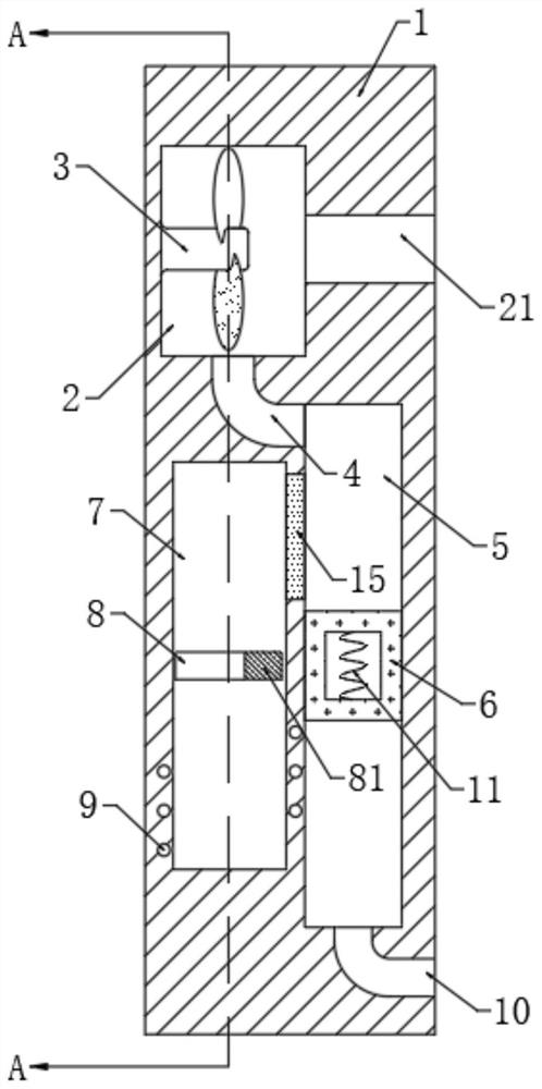
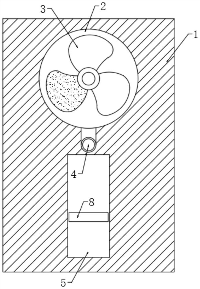
[0021] refer to Figure 1-2 , an energy-saving household air cleaner, comprising a base 1, the side wall of the base 1 is provided with an air extraction groove 2, an air extraction fan 3 is installed on the inner wall of the air extraction groove 2, and the installation method of the air extraction fan 3 is The existing mature technical means will not be described in detail here.

[0022] The side wall of the base 1 is provided with an air inlet 21 communicating with the suction tank 2 , and the lower end of the base 1 is provided with a filter tank 5 , and the filter tank 5 communicates with the suction tank 2 through an exhaust pipe 4 . It should be noted that the air inlet 21 is arranged at the axial center of the air extraction fan 3 , and the air inlet end of the exhaust pipe 4 is arranged at the inner bottom of the air extraction groove 2 .

[0023] A hollow filter layer 6 is embedded in the filter tank 5 , and a first spring 11 is embedded in the hollow filter layer 6...

Embodiment 2

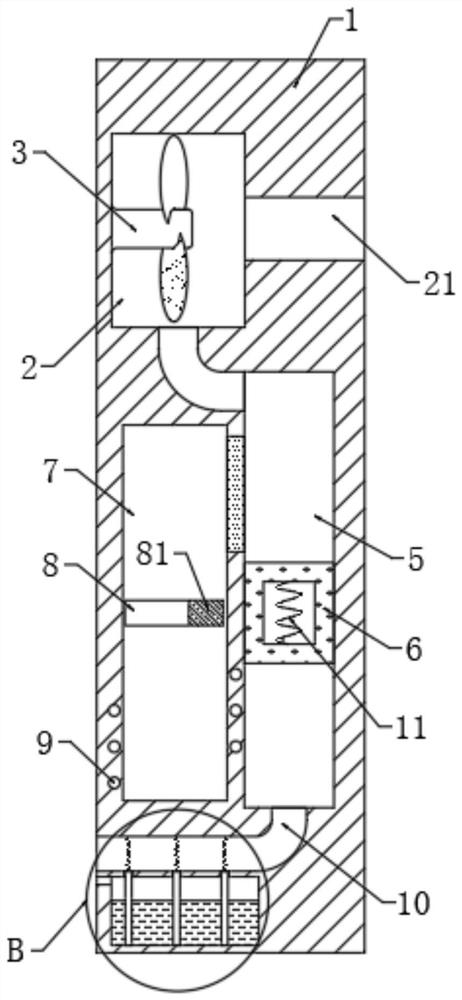
[0032] refer to Figure 3-4 , different from Embodiment 1, the lower end of the base 1 is provided with a liquid storage chamber 12, the side wall of the base 1 is provided with a water injection port 121 communicating with the liquid storage chamber 12, and the bottom of the liquid storage chamber 12 is fixedly arranged with multiple A water-absorbing bar 13, the upper end of each water-absorbing bar 13 is all fixedly connected with the second spring 14 made of iron, and the surface of the second spring 14 is fixedly connected with water-absorbing velvet.

[0033] It should be noted that both the water-absorbent strip 13 and the water-absorbent velvet are made of high-molecular water-absorbent resin, and the hydrophilic groups in its structure endow it with strong water absorption, so as to ensure that the water on the water-absorbent velvet can be fully recovered after being shaken. Timely addition.

[0034] In this embodiment, when the weather is hot or the air is dry, an ...


PUM


Abstract

The invention discloses an energy-saving household air purifier. The energy-saving household air purifier comprises a base, an air exhaust groove is formed in the side wall of the base, an air exhaustfan is installed on the inner wall of the air exhaust groove, an air inlet communicating with the air exhaust groove is formed in the side wall of the base, a filter groove is formed in the lower endof the base, a filter groove is formed in the base and communicates with the air exhaust groove through an exhaust pipe, a hollow filter layer is embedded in the filter groove, a first spring is embedded in the hollow filter layer, a sliding groove is formed in the side wall of the base, a driving device for driving the first spring to continuously stretch out and draw back is installed in the sliding groove, and an air outlet communicating with the filter groove is formed in the side wall of the base. According to the energy-saving household air purifier, by causing the hollow filter layer to shake continuously, large-particle dust above the hollow filter layer can be shaken off rapidly, the filter area of the hollow filter layer is increased, the filter effect of the hollow filter layeris improved, the air exhaust resistance of the air exhaust fan is reduced, electric energy is saved, and damage to the air exhaust fan is avoided.

Description

technical field [0001] The invention relates to the technical field of household appliances, in particular to an energy-saving household air purifier. Background technique [0002] Air purifiers, also known as "air cleaners", air fresheners, and purifiers, refer to the ability to absorb, decompose, or transform various air pollutants. [0003] Household air purifiers generally use filter elements to absorb and filter pollutants to achieve the purpose of purifying the air. After this kind of air purifier is used for a long time, some large particles of dust and other dirt will adhere to the filter element, which will block the mesh of the filter element and reduce a large amount of filter area of ​​the filter element, resulting in a greatly reduced filtration efficiency. Increasing the resistance of the exhaust fan when extracting air not only consumes electric energy, but also causes damage to the exhaust fan motor. Therefore, this application document proposes an energy-s...

Claims


Application Information

Patent Timeline
Patent Type & Authority Applications(China)
IPC IPC(8): F24F3/16F24F5/00F24F6/12F24F13/28B01D29/72B03C3/04
CPCB01D29/72B03C3/04F24F5/0035F24F6/12F24F13/28Y02B30/54
Inventor 毛学敏
Owner 毛学敏
Learn More