A reusable external wall scaffolding device

A technology for scaffolding and exterior walls, which is applied to the accessories of scaffolding, building structure support, and building structure support. It can solve the problems of slow construction progress, inability to connect stably, and high construction requirements, and achieve lower precision requirements and facilitate all-round adjustments. Easy to adjust the effect

Active Publication Date: 2022-06-24
JIANGSU PROVINCIAL CONSTR GRP CO LTD
View PDF1 Cites 0 Cited by
  • Summary
  • Abstract
  • Description
  • Claims
  • Application Information

AI Technical Summary

Problems solved by technology

[0003] In order to improve the stability of scaffolding, Chinese patent application No. 201721367213.3 discloses a revolvable external wall scaffolding device, which connects and fixes the scaffolding with pre-embedded flat steel through bolts during use, although the stability is improved , but the construction requirements are high, such as a slight deviation between the pre-embedded position and the installation position of the scaffold, which will cause the two to be unable to connect stably, and the construction progress will be slow, so it needs to be optimized

Method used


Image

  • A reusable external wall scaffolding device
  • A reusable external wall scaffolding device
  • A reusable external wall scaffolding device

Examples


Embodiment 1

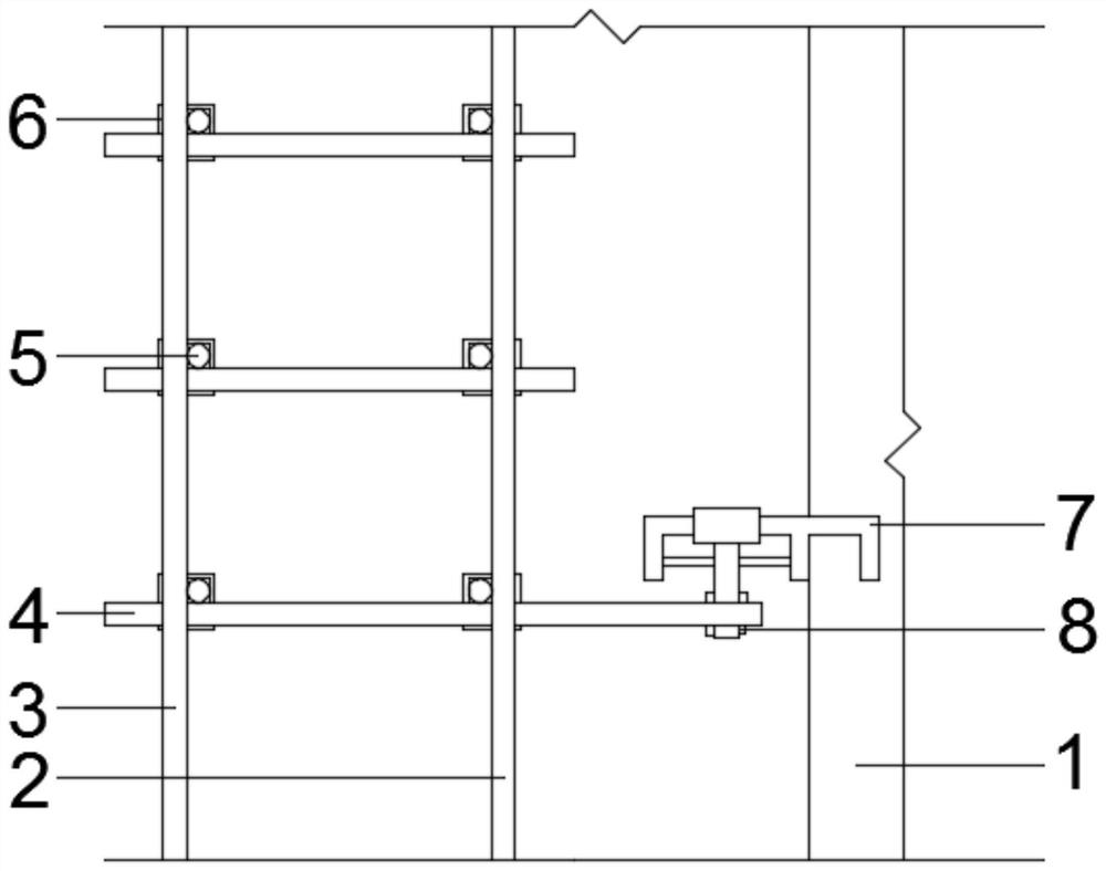
[0021] like Figure 1-4 The shown revolvable external wall scaffolding device includes a building external wall 1 and a scaffold, and the scaffold includes a plurality of first vertical rods 2 and second vertical rods 3. The first vertical rods 2 and the second vertical rods A first connecting fastener 6 is fixedly installed on the vertical rod 3, and a first horizontal rod 4 and a second horizontal rod 5 are fixedly installed in the first connecting fastener 6. For details, please refer to figure 1 That is, the first vertical bar 2 and the second vertical bar 3 are connected by the first cross bar 4, and the adjacent first vertical bar 2 and the adjacent second vertical bar 3 are respectively connected by the second horizontal bar 5, thereby A complete scaffold is formed; an adjustable tie mechanism 7 is fixedly installed in the outer wall 1 of the building, and the adjustable tie mechanism 7 is fixedly connected to the scaffold through a second connecting fastener 8, specifi...

Embodiment 2

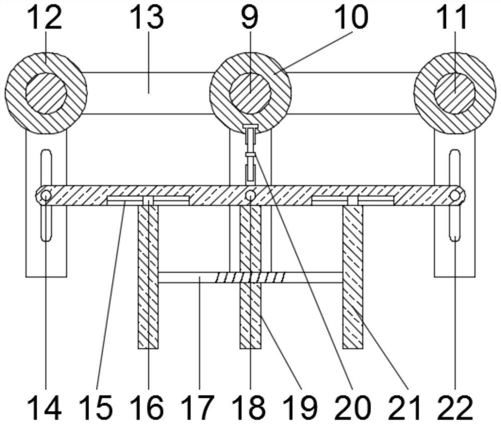
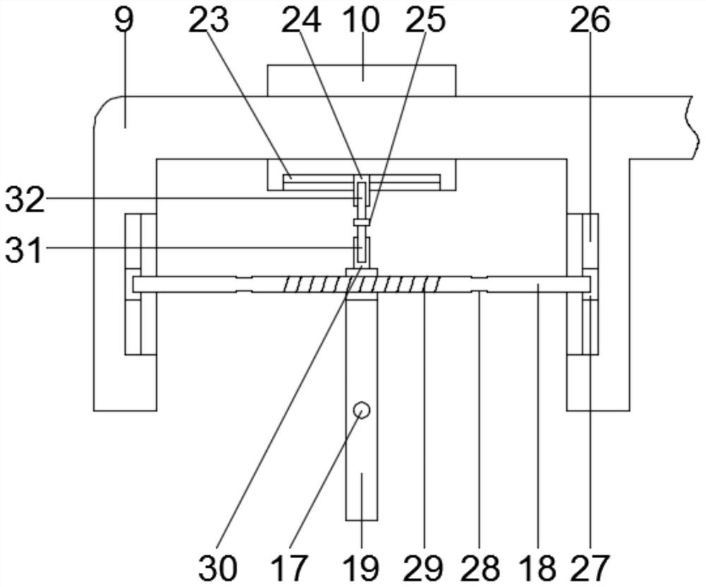
[0025]This embodiment is further optimized on the basis of Embodiment 1. In order to realize any adjustment in the horizontal direction, the horizontal adjustment mechanism further includes a first adjustment rod 17 , and the first adjustment rod 17 is arranged in the fixed rod 19 and Threaded connection with it, both ends of the first adjusting rod 17 are respectively installed with movable rods 21 rotatably connected with it, and the upper end of the movable rod 21 is slidably connected with the lifting plate. Specifically, the bottom of the lifting plate is provided with a first chute. 15. A first sliding block 16 slidably connected to the first sliding groove 15 is installed therein, and the bottom of the first sliding block 16 is fixedly connected to the upper end of the movable rod 21 , that is, the first adjusting rod 17 and the second adjusting rod 18 The adjustment directions of the horizontal plane are perpendicular to each other. When the first adjustment rod 17 is r...


PUM


Abstract

The invention relates to a revolvable external wall scaffolding device, which belongs to the technical field of construction and includes building external walls and scaffolding. The scaffolding includes a plurality of first vertical rods and second vertical rods. The first vertical rods Both the first connecting fastener and the second vertical rod are fixedly installed, the first connecting fastener is fixedly installed with the first crossbar and the second crossbar, and the building exterior wall is fixedly installed with an adjustable tie mechanism, the adjustable knot mechanism is fixedly connected to the scaffold through the second connecting fastener; the present invention connects and fixes the scaffold with the building exterior wall by setting an adjustable knot mechanism, which is convenient for all-round adjustment of the connection point, thereby reducing the The accuracy requirements when the scaffolding is connected to the exterior wall of the building during the construction process improve the installation efficiency and stability of the scaffolding, making it easier to adjust and more practical.

Description

technical field [0001] The invention relates to the technical field of construction, in particular to a tie-down device for outer wall scaffolding that can be used in turnaround. Background technique [0002] Scaffolding is a working platform set up to ensure the smooth progress of each construction process. According to the erection position, it is divided into outer scaffolding and inner scaffolding; according to different materials, it can be divided into wooden scaffolding, bamboo scaffolding, steel pipe scaffolding; Hanging scaffolding, pick-up scaffolding, climbing scaffolding. [0003] In order to improve the stability of the scaffolding, the Chinese patent application No. 201721367213.3 discloses a revolvable external wall scaffolding tie device, which connects and fixes the scaffolding with the pre-embedded flat steel through bolts during use, although the stability is improved. , but the construction requirements are high, such as a slight deviation between the p...

Claims


Application Information

Patent Timeline
Patent Type & Authority Patents(China)
IPC IPC(8): E04G5/04
CPCE04G5/046
Inventor 祝捷陈源源姬长玉常凯庆张允亮李国平周明柏李振伟罗建英王中凯邢政王兆军张贵星刘亚鸿张燕赵兴旺李亚光刘京超赵本超杨森池崇玉王俊斌
Owner JIANGSU PROVINCIAL CONSTR GRP CO LTD
Why Eureka
Try Eureka