
A winding device for a tape-shaped winding photoelectric transmission composite cable

A technology of photoelectric transmission and winding device, which is applied in the directions of transportation and packaging, conveying filamentous materials, and thin material processing, etc., which can solve the problems of low production efficiency, high labor intensity, and poor winding stability of spiral cables, and achieve Fast and efficient effect

Active Publication Date: 2021-02-23
SUZHOU YINUOBEI NEW MATERIAL TECH CO LTD
View PDF10 Cites 0 Cited by
  • Summary
  • Abstract
  • Description
  • Claims
  • Application Information

AI Technical Summary

Problems solved by technology

[0002] The spiral cable is formed by winding and thermal processing of the cable, and finally cooling. The existing spiral winding of the cable is usually formed by ordinary winding rods through the rotating mechanism and artificially assisted winding. Due to the elasticity of the cable itself, it is During the cable winding process, it is necessary to manually wind and fix the two ends of the cable. The stability of this spiral cable winding is poor, the labor intensity is high, and the production efficiency is low.

Method used


Image

  • A winding device for a tape-shaped winding photoelectric transmission composite cable
  • A winding device for a tape-shaped winding photoelectric transmission composite cable
  • A winding device for a tape-shaped winding photoelectric transmission composite cable

Examples


Embodiment Construction

[0024] The present invention will be further described below in conjunction with specific embodiment and accompanying drawing, set forth more details in the following description so as to fully understand the present invention, but the present invention can be implemented in many other modes different from this description obviously, Those skilled in the art can make similar promotions and deductions based on actual application situations without violating the connotation of the present invention, so the content of this specific embodiment should not limit the protection scope of the present invention.

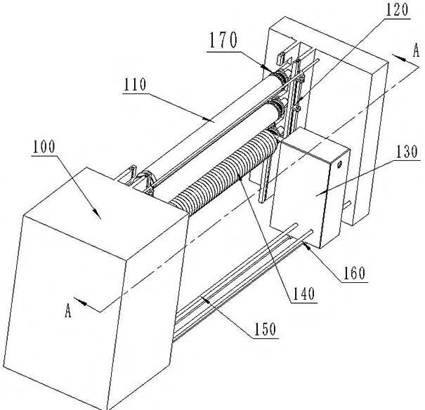
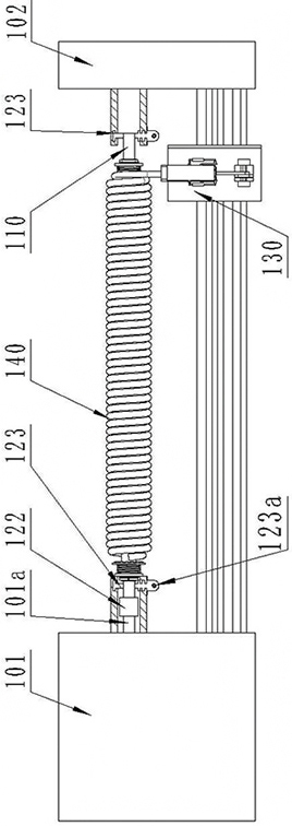
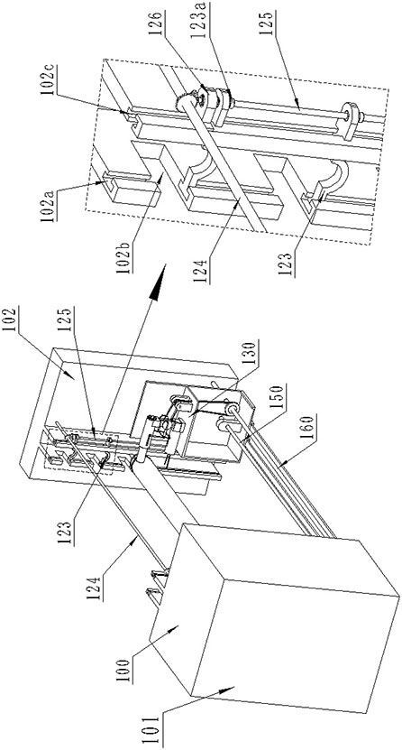
[0025] Such as figure 1 As shown, a tape-shaped winding type photoelectric transmission composite cable winding device includes: a frame 100, a winding rod 110, an elastic clamping head 170, a feeding mechanism 120, a moving mechanism 130, a screw shaft 150, and a light rod shaft 160.

[0026] Such as figure 2 , 3 , 4, the frame 100 includes a power box 101 on the left sid...


PUM


Abstract

The invention relates to the technical field of cable production, in particular to a tape-shaped winding type photoelectric transmission composite cable winding device, which includes: a frame, a winding rod, an elastic clamping head, a feeding mechanism, a moving mechanism, a screw shaft, Light rod shaft, the frame includes a power box on the left side for providing power and a carrier for carrying the feeding mechanism, the carrier has T-shaped notches, cross-shaped notches and rectangular notches, and the T-shaped notches The cross notch is located on both sides of the carrier and penetrates to the bottom to install the semi-circular bracket. The rectangular notch is located on one side of the carrier and runs through the T-shaped notch on the same side and cuts it evenly into several equal parts. In part, the present invention can realize continuous winding of the cable under the cooperation of the elastic clamping head and the moving mechanism through the design of the clamping head and the moving mechanism, and realize automatic fixing and automatic cutting during the continuous winding process, and can be continuously wound for more A spiral cable, fast and efficient.

Description

technical field [0001] The invention relates to the technical field of cable production equipment, in particular to a ribbon winding type optoelectronic transmission composite cable winding device. Background technique [0002] The spiral cable is formed by winding and thermal processing of the cable, and finally cooling. The existing spiral winding of the cable is usually formed by ordinary winding rods through the rotating mechanism and artificially assisted winding. Due to the elasticity of the cable itself, it is During the cable winding process, it is necessary to manually wind and fix the two ends of the cable. This kind of spiral cable winding has poor stability, high labor intensity and low production efficiency. Contents of the invention [0003] Therefore, the present invention is made in view of the above problems. The purpose of the present invention is to provide a tape winding type optoelectronic transmission composite cable winding device that can continuous...

Claims


Application Information

Patent Timeline
Patent Type & Authority Patents(China)
IPC IPC(8): B65H75/28B65H54/40B65H75/32
CPCB65H54/40B65H75/28B65H75/32
Inventor 刘雷邵良
Owner SUZHOU YINUOBEI NEW MATERIAL TECH CO LTD
Learn More