A bogie for a rail vehicle and a rail vehicle

A bogie and axle technology, applied in the field of rail vehicles, can solve the problems of complex structure and large mass of motor direct drive bogies

Active Publication Date: 2021-05-04
CRRC TANGSHAN CO LTD
View PDF7 Cites 0 Cited by
  • Summary
  • Abstract
  • Description
  • Claims
  • Application Information

AI Technical Summary

Problems solved by technology

[0006] The embodiment of the present application provides a bogie for a rail vehicle and a rail vehicle to solve the technical problems of the existing motor direct drive bogie with complex structure and high mass

Method used


Image

  • A bogie for a rail vehicle and a rail vehicle
  • A bogie for a rail vehicle and a rail vehicle
  • A bogie for a rail vehicle and a rail vehicle

Examples


Embodiment 1

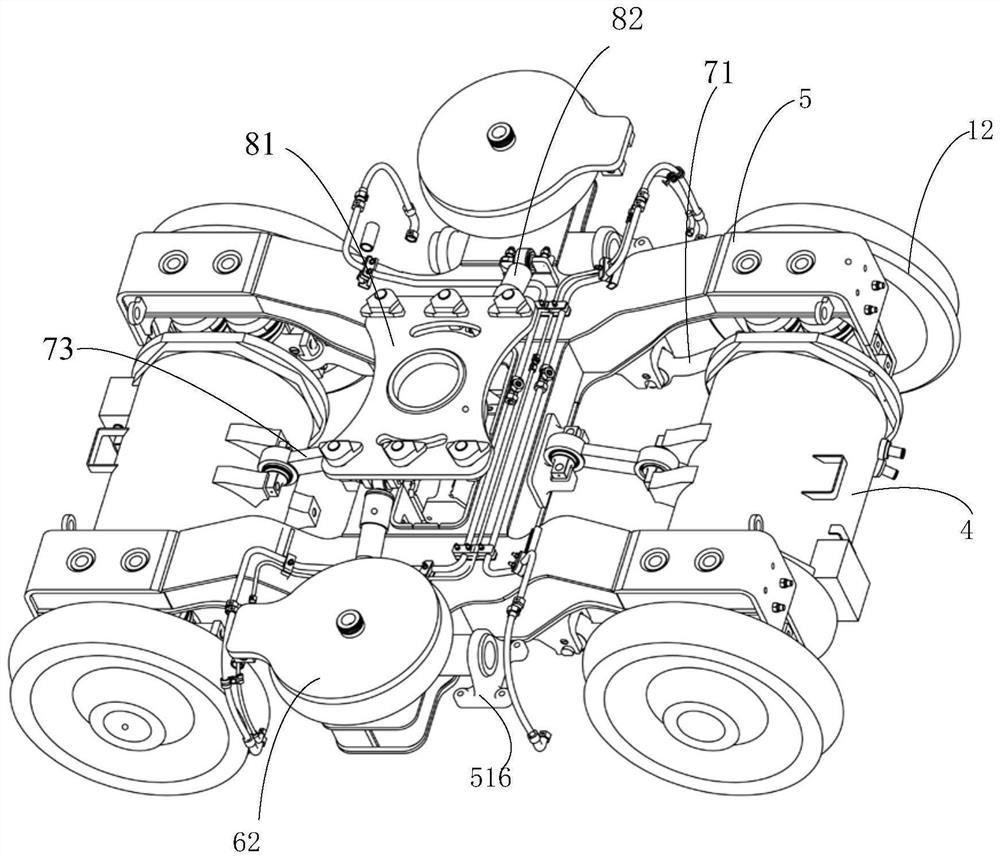
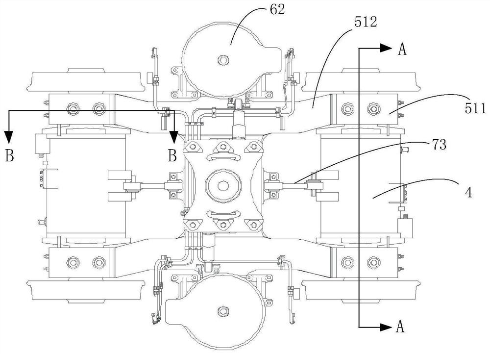
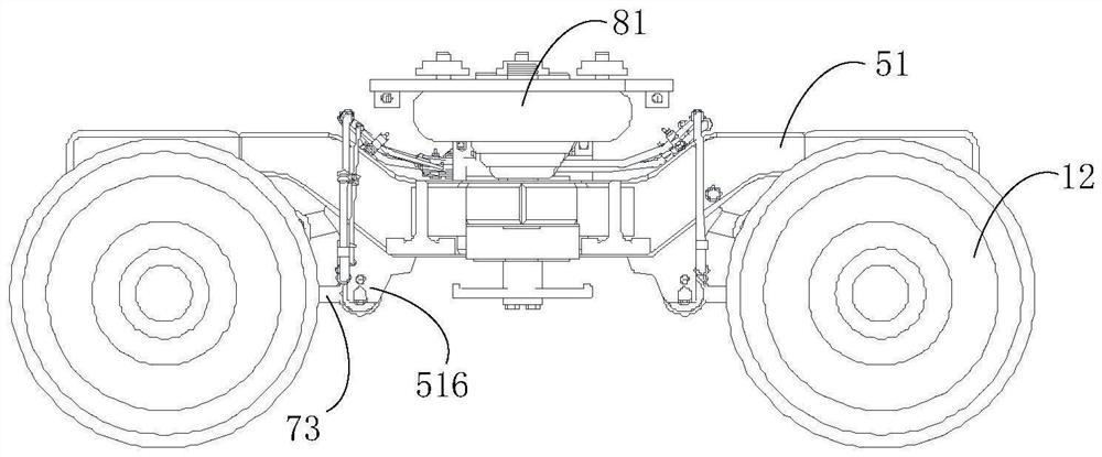
[0053] figure 1 It is a three-dimensional schematic diagram of a bogie for a rail vehicle according to an embodiment of the present application; figure 2 for figure 1 A top view of the bogie shown; image 3 for figure 1 Side view of the bogie shown; Figure 4 for figure 1 Front view of the bogie shown; Figure 5 for figure 2 A-A sectional view of the bogie shown; Figure 6 for figure 2B-B sectional view of the bogie shown; Figure 7 for figure 2 Stereo view of bogie wheel set and permanent magnet direct drive motor installed as one; Figure 8 for figure 1 A perspective view of the motor end cover of the bogie shown; Figure 9 for Figure 8 A schematic view of another angle of the motor end cover shown; Figure 10 for Figure 9 The C-C sectional view of the motor end cover shown; Figure 11 for figure 1 A perspective view of the wheel-to-axlebox of the bogie shown; Figure 12 for Figure 11 Another perspective view of the wheel-to-axlebox shown.

[0054]...

Embodiment 2

[0107] The bogie for a rail vehicle according to the embodiment of the present application has the following features on the basis of the first embodiment.

[0108] implementation, such as figure 1 , figure 2 , image 3 , Figure 4 , Figure 5 , Figure 13 , Figure 14 , Figure 15 and Figure 16 As shown, the bogie also includes a frame 5 and a series of suspension devices; the frame 5 includes:

[0109] Two side beams 51 arranged in parallel, the two ends of the side beams 51 are two first series installation parts 511, the middle is a connection part 512 connecting the two first series installation parts, the connection of the two side beams portions 512 are recessed toward each other in the lateral direction;

[0110] A beam 52, connecting the connecting portion 512 of the two side beams;

[0111] Wherein, the primary suspension device is installed on the wheel set axle box 2, the primary mounting part 511 of the side beam is located on the primary suspension de...

Embodiment 3

[0146] An embodiment of the present application provides a rail vehicle, including the bogie described in the first or second embodiment.


PUM


Abstract

An embodiment of the present application provides a bogie for a rail vehicle and the rail vehicle. The bogie, the wheel set, the wheel set includes the axle and two wheels, the axle is the axle of the hollow shaft structure; the two wheel set axle boxes and the two axle boxes use bearings, the inner rings of the axle boxes are fixed on the axle shaft and It is located between two wheels; the wheel-to-axlebox is sleeved on the outer ring of the bearing for the axlebox; the permanent magnet direct drive motor is set between the two wheel-to-axleboxes, and the permanent magnet direct-drive motor includes a motor casing and a rotor , the stator and two motor end covers, the two motor end covers are fixed at both ends of the motor shell, the motor end cover has an end cover shaft hole; the rotor is fixed on the outer peripheral surface of the axle to directly drive the axle, the stator and the motor shell are fixed It is integrated and sleeved on the outside of the rotor. The rail vehicle comprises the bogie described above. The embodiment of the present application solves the technical problems of the existing motor direct drive bogie with complex structure and high mass.

Description

technical field [0001] The present application relates to the technical field of rail vehicles, and in particular, relates to a bogie for rail vehicles and a rail vehicle. Background technique [0002] The traditional bogie drive system adds a transmission gearbox and a coupling on the basis of the traction motor. The gear meshing friction pairs and gear couplings of the gear transmission will generate different degrees of noise and vibration during the meshing process; the transmission process It will also cause power loss and reduce efficiency; in addition, the gear meshing friction pair will gradually wear out, and maintenance and replacement will increase the operation and maintenance costs, etc., which also lead to a large quality of the bogie. [0003] The motor direct drive bogie refers to the bogie that directly transmits the output torque or force of the traction motor to the wheel set by removing the transmission parts between the motor and the wheel set of the tra...

Claims


Application Information

Patent Timeline
Patent Type & Authority Patents(China)
IPC IPC(8): B61F5/26B61C9/50
CPCB61C9/50B61F5/26
Inventor 张继林郑建科刘春海张丽君王乃胜王大海王伟
Owner CRRC TANGSHAN CO LTD
Why Eureka
Try Eureka