Conductive bar sequential punching machine

A technology of punching machine and conductive row, which is used in boring/drilling, drilling/drilling equipment, metal processing machinery parts, etc. and other issues to achieve the effect of increasing mobility

Active Publication Date: 2020-09-25
绍兴舟泽新材料股份有限公司
View PDF6 Cites 2 Cited by
  • Summary
  • Abstract
  • Description
  • Claims
  • Application Information

AI Technical Summary

Problems solved by technology

[0003] The existing conductive row punching machine has the following problems: 1. The existing conductive row punching machine can only have one machine and one hole. If more holes are punched on the conductive row, the puncher needs to be replaced, and one machine cannot be porous; 2. Dust will be left due to metal cutting when drilling, but the existing punching machine cannot clean the dust, resulting in low drilling efficiency for a long time

Method used


Image

  • Conductive bar sequential punching machine
  • Conductive bar sequential punching machine
  • Conductive bar sequential punching machine

Examples


Embodiment Construction

[0037] The following will clearly and completely describe the technical solutions in the embodiments of the present invention with reference to the accompanying drawings in the embodiments of the present invention. Obviously, the described embodiments are only some, not all, embodiments of the present invention. Based on the embodiments of the present invention, all other embodiments obtained by persons of ordinary skill in the art without making creative efforts belong to the protection scope of the present invention.

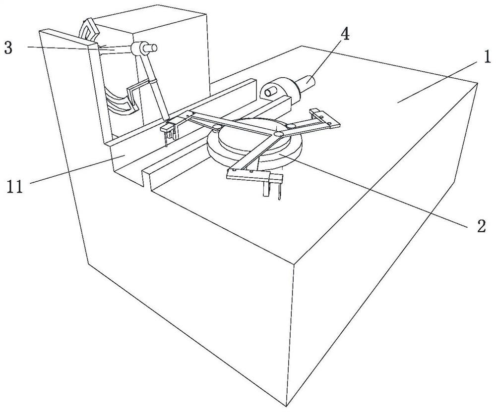
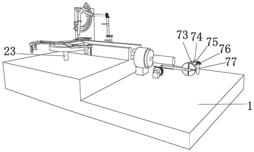
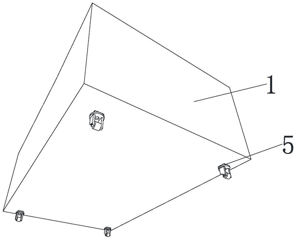
[0038] see Figure 1-Figure 8 , the present invention provides a kind of technical scheme: conductive row sequential punching machine, comprises punching machine case 1, and the upper surface of punching machine case 1 is provided with rectangular groove 11, is provided with punching device on the punching machine case 1, punches The hole device includes a disk 12, three bearings 121 are movably connected on the disk 12, a rectangular connecting rod 2 61 is mo...


PUM


Abstract

The invention discloses a conductive bar sequential punching machine, and relates to the technical field of conductive bar sequential punching machines. The machine comprises a punching machine case,and a rectangular groove is formed in the upper surface of the punching machine case. The punching machine case is provided with a punching device. The punching device comprises a disk I. The disk I is movably connected with three bearings I. The three bearings I are all movably connected with rectangular connecting rods II, the three rectangular connecting rods II are all movably connected with bearings VI. The three bearings VI are all movably connected with rectangular blocks I, and every two springs are movably connected with a rectangular block II. The sliding of a piston rod drives the sliding of a piston. The sliding of the piston squeezes air in a piston tube. Air in the piston tube rushes out from an air outlet to blow away dust left by punching in the rectangular groove, therebymaking the rectangular groove cleaner, and the problem of too much dust in an existing punching device is solved.

Description

technical field [0001] The invention relates to the technical field of conductive row sequential punching machines, in particular to a conductive row sequential punching machine. Background technique [0002] The bus bar refers to the copper bar or aluminum bar connecting the main switch in the electric cabinet and the switches in each branch circuit in the power supply system. The busbar is generally a solid structure with a rectangular cross section. According to incomplete statistics, the annual usage of busbars in low-voltage switchboards and switchgears is about 300,000 tons. However, as the price of non-ferrous metal copper rises and fluctuates daily, the cost of busbars accounts for 20% to 40% of the total cost of switchboards and switchgears. In order to reduce the overall manufacturing cost of switchboards, switch cabinets, etc., one of the solutions provided in the prior art is to use copper-aluminum composite bars. However, copper and aluminum alloys will under...

Claims


Application Information

Patent Timeline
Patent Type & Authority Applications(China)
IPC IPC(8): B23B41/00B23B39/20B23B47/00B23B47/30B23Q3/06B23Q5/10B23Q5/48B23Q11/00
CPCB23B39/20B23B41/00B23B47/00B23B47/30B23Q3/06B23Q5/10B23Q5/48B23Q11/005
Inventor 李玉成
Owner 绍兴舟泽新材料股份有限公司
Why Eureka
Try Eureka