An automatic circuit board pin cutting equipment
A cutting equipment and circuit board technology, applied in the field of circuit board processing, can solve the problems of uneven trimming, inaccurate trimming position, easy trimming to components and circuit boards, etc., and achieve the effect of safety guarantee and high degree of automation
- Summary
- Abstract
- Description
- Claims
- Application Information
AI Technical Summary
Problems solved by technology
Method used
Image

Examples
Embodiment 1
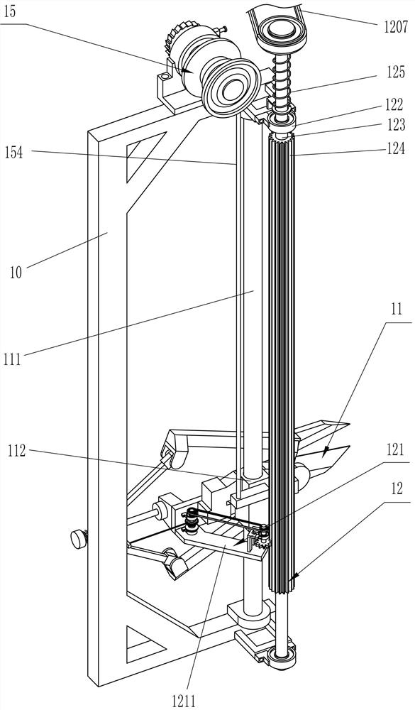
[0034] A kind of automatic circuit board pin cutting equipment, such as Figure 1-4 As shown, it includes a mounting frame 1, a guide block 101, a collection bucket 102, a support frame 2, a connecting block 3, a first guide rail 4, a first guide sleeve 5, a connecting plate 6, a placement frame 7, fastening bolts 8, fixing Frame 9, connecting frame 10, thread trimming device 11, shearing driving device 12 and driving assembly 13, specifically:
[0035] Four sets of guide blocks 101 are connected to the front side above the lower side wall of the installation frame 1, and a collecting bucket 102 is placed between the guide blocks 101. A support frame 2 is connected above the upper side wall of the installation frame 1, and the inside of the support frame 2 is connected to a connecting block. 3. The first guide rail 4 is connected between the connecting blocks 3, the first guide sleeve 5 is slidably connected to the first guide rail 4, the front side of the first guide sleeve 5...
Embodiment 2
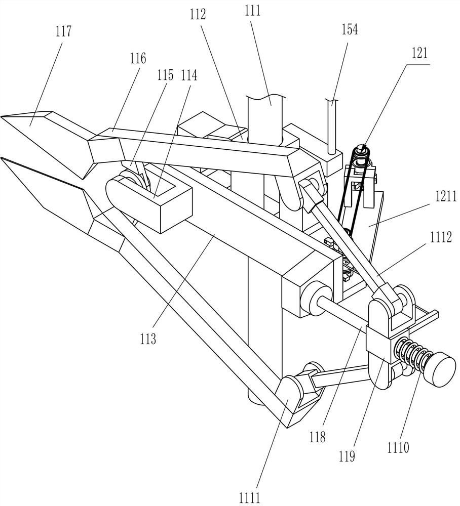
[0038] On the basis of Example 1, such as Figure 4-11 As shown, the thread cutting device 11 includes a second guide rail 111, a second guide sleeve 112, a mounting plate 113, a connecting seat 114, a rotating piece 115, a clamp arm 116, a blade 117, a third guide rail 118, a third guide sleeve 119, The first elastic member 1110, the movable seat 1111 and the movable rod 1112 are specifically:
[0039] A second guide rail 111 is connected between the upper and lower sides of the connecting frame 10, the second guide rail 111 is slidably connected with a second guide sleeve 112, the rear side of the second guide sleeve 112 is connected with a mounting plate 113, and the rear side of the mounting plate 113 The right side is connected with a connecting seat 114, and the inner side of the connecting seat 114 is hingedly connected with two sets of rotating pieces 115. The rotating pieces 115 intersect with each other, and the outside of the rotating pieces 115 is connected with a ...
Embodiment 3
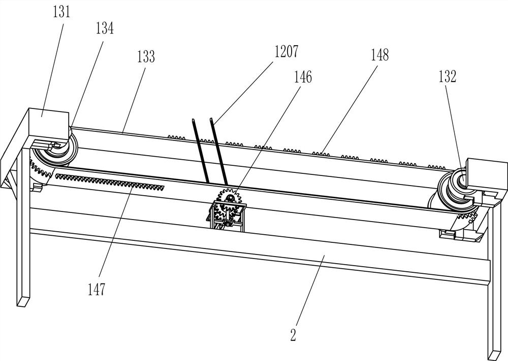
[0054] On the basis of Example 2, such as Figure 4 , 8 , 9, 10, 12 and 13, also includes a propulsion device 14, the propulsion device 14 includes a rack 141, the seventh rotating shaft 142, the eighth rotating shaft 143, the second gear transmission assembly 144, the third round gear 145, The fourth circular gear 146, the second toothed belt 147 and the third toothed belt 148 are specifically:
[0055] The upper side of the upper placing frame 7 is provided with a propulsion device 14, which is used to automatically push the placing frame 7 to the left for a certain distance when the thread trimmer 11 cuts once, and the upper rear of the upper placing frame 7 is connected with a rack 141, the seventh rotating shaft 142 is rotatably connected to the upper side and rear of the support 1201, the eighth rotating shaft 143 is rotatably connected to the upper side and front of the support 1201, and the second gear transmission assembly 144 is connected between the seventh rotatin...
PUM
 Abstract
Description
Claims
Application Information
 - R&D
- Intellectual Property
- Life Sciences
- Materials
- Tech Scout
- Unparalleled Data Quality
- Higher Quality Content
- 60% Fewer Hallucinations
Browse by: Latest US Patents, China's latest patents, Technical Efficacy Thesaurus, Application Domain, Technology Topic, Popular Technical Reports.
© 2025 PatSnap. All rights reserved.Legal|Privacy policy|Modern Slavery Act Transparency Statement|Sitemap|About US| Contact US: help@patsnap.com