Millimeter wave terahertz wave multimode orbital angular momentum beam scanning antenna and method

A beam scanning and antenna technology, applied in the field of orbital angular momentum, can solve the problems of difficult to achieve radiation direction, narrow operating bandwidth, large array size, etc., to avoid system loss, improve purity, and reduce reflection.

Active Publication Date: 2020-09-22
PEKING UNIV
View PDF6 Cites 2 Cited by
  • Summary
  • Abstract
  • Description
  • Claims
  • Application Information

AI Technical Summary

Problems solved by technology

In the microwave band, OAM modes can be generated by structures such as metasurfaces, element antenna arrays, and helical antennas, but there are still many problems to be solved: 1. The size of the array is too large, which is not conducive to the integration of the structure
2. Due to the resonance effect of the metasurface structure depending on the unit structure, the working bandwidth is narrow
3. Both the unit structure and the element antenna structure need to produce OAM, which depends on the phase change between adjacent units. It is necessary to accurately design the unit distribution for a specific OAM mode, and it is difficult to adjust.
4. The regulation of the OAM mode only has the regulation of the mode distribution, and the radiation direction is difficult to realize

Method used


Image

  • Millimeter wave terahertz wave multimode orbital angular momentum beam scanning antenna and method
  • Millimeter wave terahertz wave multimode orbital angular momentum beam scanning antenna and method
  • Millimeter wave terahertz wave multimode orbital angular momentum beam scanning antenna and method

Examples


Embodiment Construction

[0037] The present invention will be further elaborated below through specific embodiments in conjunction with the accompanying drawings.

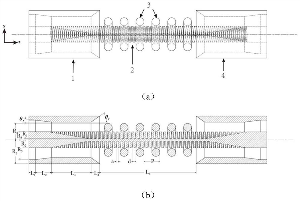
[0038] Such as figure 1 As shown, the artificial surface plasmon-based OAM mode beam scanning antenna of this embodiment includes: a first waveguide feeding device 1, an SSP transmission line 2, a radiation array 3, a second waveguide feeding device 4, and an array support frame; Wherein, both ends of the SSP transmission line 2 are respectively coaxially connected to the first waveguide feeder 1 and the second waveguide feeder 4; the radiation array 3 is fixed on the array support frame, and the radiation array 3 is coaxially sleeved outside the SSP transmission line 2; Both ends of the first and second waveguide feeding devices 4 are respectively connected to the coaxial line; the SSP transmission line 2 is a spiral grating, that is, a spiral rectangular groove with a consistent depth of the periodic structure is etched on the outer surf...


PUM

PropertyMeasurementUnit
Angle of inclinationaaaaaaaaaa

Abstract

The invention discloses a millimeter wave terahertz wave multimode orbital angular momentum beam scanning antenna and method. According to the invention, a waveguide feed device is adopted to converta TEM mode in a coaxial line into an SSP mode, and the SSP mode is propagated along the surface of an SSP transmission line and carries an OAM mode; under the diffraction action of a radiation array loaded outside the SSP transmission line, the wave vector of the SSP mode is superposed with the harmonic wave vector generated by diffraction to generate a frequency spectrum shifting effect, therebyconverting the SSP mode with the OAM mode into a free space radiation wave, realizing OAM mode radiation, and working in different frequency bands; the radiation direction corresponds to the working frequency, so that the radiation direction of the OAM mode is controlled by controlling the working frequency; and the rotation direction of the OAM mode is consistent with the chirality of a spiral grating. The structure is compact, and a plurality of unit arrays are not needed; the robustness of the system is high, and only the spiral characteristics of the spiral grating need to be maintained; the waveguide feed device is simple, only coaxial port feed is needed, and a complex feed network is not needed.

Description

technical field [0001] The invention relates to orbital angular momentum technology, in particular to a millimeter wave-terahertz wave multi-mode orbital angular momentum beam scanning antenna and method. Background technique [0002] Orbital angular momentum (OAM) is one of the research hotspots in the current field, which has a spiral wave front. OAM modes are widely used in communication systems due to the orthogonality between different modes of OAM, which can greatly improve channel capacity in communication systems. In addition, OAM also has a wide range of applications in particle manipulation, quantum coding, imaging, etc. Although OAM has many potential application scenarios, how to efficiently generate and manipulate OAM patterns has not been effectively resolved. There are many methods for stimulating the OAM mode at present. In the optical band, the OAM mode can be generated by structures such as transmission type or reflection type spiral phase plate, hologra...

Claims


Application Information

Patent Timeline
IPC IPC(8): H01Q1/50H01Q3/22H01Q1/36H01Q5/28H01Q9/27
CPCH01Q1/36H01Q1/50H01Q3/22H01Q9/27H01Q5/28
Inventor 杜朝海朱娟峰张子文包路遥刘濮鲲
Owner PEKING UNIV
Why Eureka
Try Eureka