
Radiator for power device and power device

A technology of power devices and heat sinks, which is applied in semiconductor/solid-state device components, electric solid-state devices, semiconductor devices, etc., and can solve problems such as failure of power devices

Pending Publication Date: 2020-09-22
GREE ELECTRICAL APPLIANCE WUHU +1
View PDF0 Cites 2 Cited by
  • Summary
  • Abstract
  • Description
  • Claims
  • Application Information

AI Technical Summary

Problems solved by technology

[0004] In view of this, the present invention provides a heat sink for power devices and a power device, which can solve the problem in the prior art that the power device is likely to fail after the mounting surface of the heat sink contacts the surface of the power device. Specifically,

Method used


Image

  • Radiator for power device and power device
  • Radiator for power device and power device

Examples


Embodiment

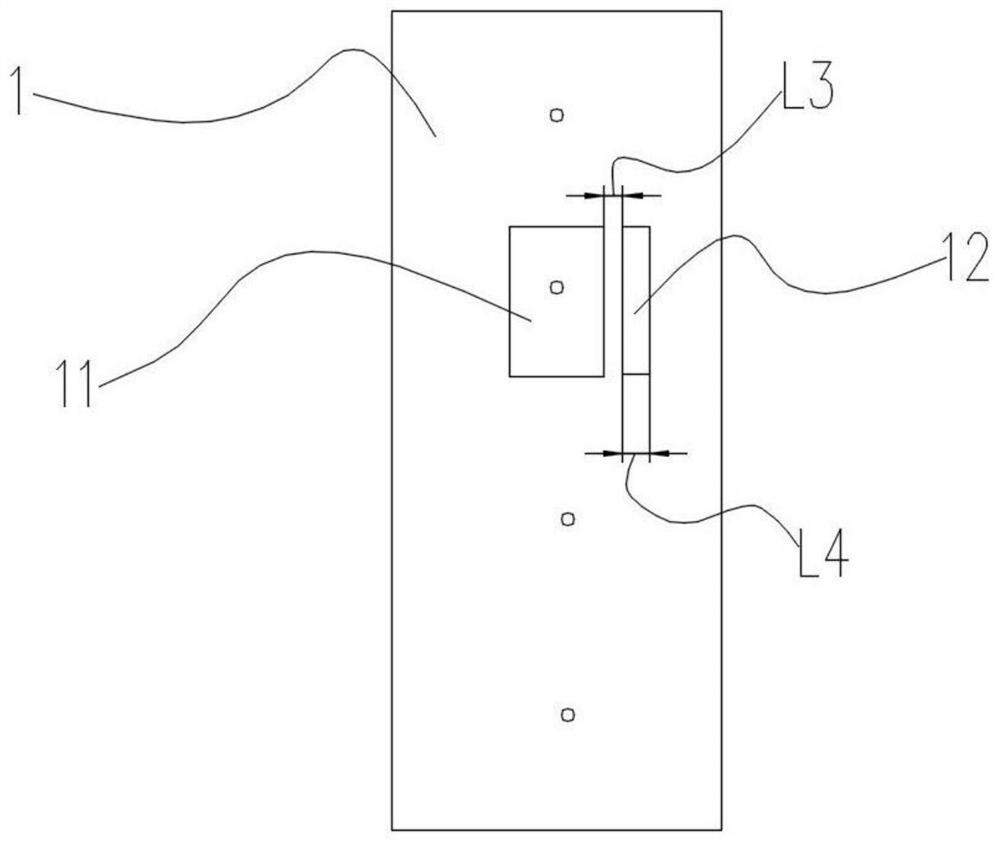
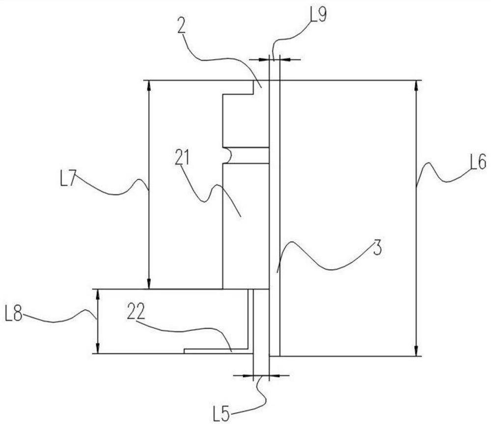
[0029] Such as Figure 1-2 As shown, the present embodiment provides a power device, the heat sink 1 combined with the power device 2 performs heat dissipation, wherein, the heat sink 1 is formed with a raised structure 11 on the contact surface with the power device 2, even if the heat sink 1 The heat dissipation surface protrudes upwards to form a mounting area for the power device 2 , and a power device mounting surface for mounting the power device 2 is formed on the mounting area formed by the raised structure 11 . Specifically, the non-metallic mounting surface formed on the upper surface of the power device 2, when the power device 2 is assembled to the radiator 1, the non-metallic mounting surface of the power device 2 and the power device mounting surface on the raised structure 11 are matched to complete the installation, wherein , the range of the height L1 of the raised structure 11 is 1.5mm-2.5mm, further, the range of the height L1 of the raised structure 11 is p...


PUM

PropertyMeasurementUnit
Heightaaaaaaaaaa
Groove depthaaaaaaaaaa
Thicknessaaaaaaaaaa

Abstract

The invention relates to a radiator for a power device and the power device. A convex structure and a groove are formed on a contact surface of the radiator and the power device, the power device is assembled on the convex structure, pins of the power device face the direction far away from the groove, so an electrical safety distance between the pins of the power device and the radiator is increased, safety problems of sparking and the like caused by small electrical safety distance of the power device are avoided, application reliability of the power device is improved, and the power deviceand the radiator operate stably.

Description

technical field [0001] The invention relates to a radiator and a power device, in particular to a radiator and a power device for a power device. Background technique [0002] Power devices are mainly used in frequency conversion inverters and other inverter circuits, and are the core components of energy conversion and transmission in the field of industrial control and automation. [0003] The temperature of this type of device is too high during operation, which is very easy to cause burnout. In order to ensure the reliability of the device, it will be assembled and contacted with the radiator in circuit application to ensure long-term reliable operation. The heat sink itself is not a part of the circuit, but if the mounting surface of the heat sink module is in contact with the surface of the power device, if the electrical clearance between the heat sink module and the metal pin is small, it will easily cause the failure of the power device, such as leakage or foreign m...

Claims


Application Information

Patent Timeline
IPC IPC(8): H01L23/40H01L23/367H05K7/20
CPCH01L23/3672H01L23/40H05K7/2039
Inventor 许勇杨俊赵晓博李学成刘小雷
Owner GREE ELECTRICAL APPLIANCE WUHU
Learn More