
Subway intelligent monitoring system and control method

An intelligent monitoring system and monitoring system technology, applied in the direction of control/regulation system, air conditioning system, non-electric variable control, etc., can solve the problem of unable to realize the linkage control of wind system and water system, only focusing on the energy consumption index of stand-alone equipment, and unable to system Energy-saving control and other issues, to achieve the effect of monitoring and controlling equipment, reducing overall energy consumption, and achieving precise control

Active Publication Date: 2020-09-22
GUANGZHOU METRO DESIGN & RES INST
View PDF12 Cites 7 Cited by
  • Summary
  • Abstract
  • Description
  • Claims
  • Application Information

AI Technical Summary

Problems solved by technology

The environment and equipment monitoring system control framework of the existing subway station does not distinguish between the environment control equipment monitoring system and the station equipment monitoring system, and is directly monitored and controlled by the environment and equipment monitoring system; it only focuses on the energy consumption indicators of stand-alone equipment , the equipment selection cannot be considered from the energy consumption index of the entire system; the system can only complete the frequency conversion operation of the single equipment under certain conditions, and cannot perform energy-saving control from the optimal point of view of the entire system; Linkage relationship. In the past, the linkage control of the wind system and the water system could not be realized in the previous lines, and they could only operate independently.

Method used


Image

  • Subway intelligent monitoring system and control method
  • Subway intelligent monitoring system and control method
  • Subway intelligent monitoring system and control method

Examples


Embodiment Construction

[0071] Embodiments of the present invention are described in detail below, and examples of the embodiments are shown in the drawings, wherein the same or similar reference numerals denote the same or similar elements or elements having the same or similar functions throughout. The embodiments described below by referring to the figures are exemplary only for explaining the present invention and should not be construed as limiting the present invention. For the step numbers in the following embodiments, it is only set for the convenience of illustration and description, and the order between the steps is not limited in any way. The execution order of each step in the embodiments can be adapted according to the understanding of those skilled in the art sexual adjustment.

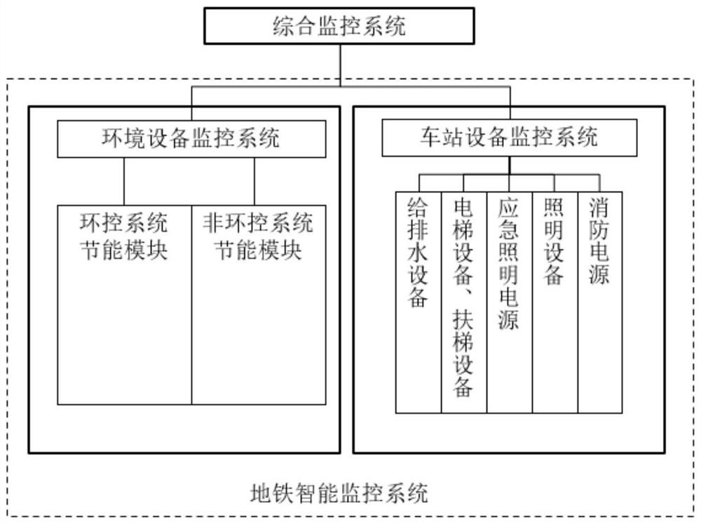
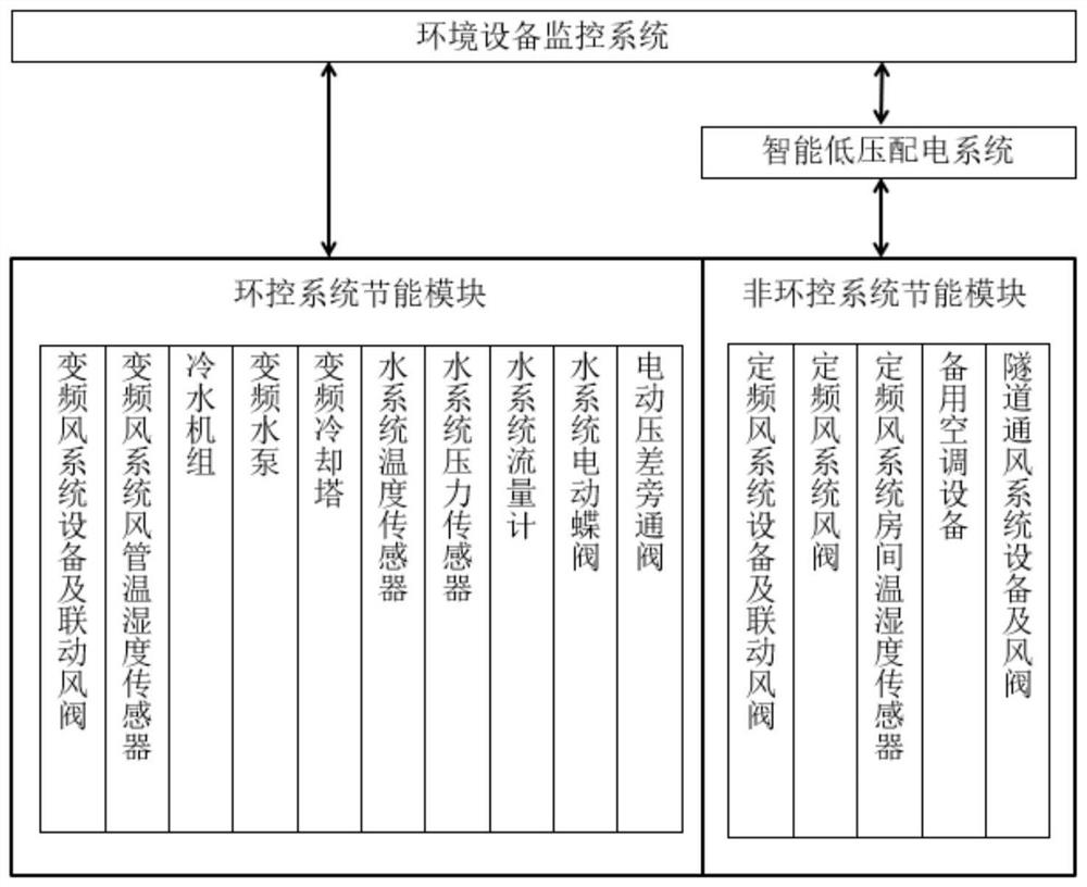
[0072] refer to figure 1 , a kind of subway intelligent monitoring system in the embodiment of the present invention, comprises environmental equipment monitoring system and station equipment monitoring syste...


PUM


Abstract

The invention discloses a subway intelligent monitoring system, which comprises an environmental equipment monitoring system used for monitoring and controlling environmental control system equipmentin a station; a station equipment monitoring system, used for monitoring and controlling station equipment; an environmental equipment monitoring system, comprising a first module used for carrying out wind-water linkage control according to an energy-saving target and a control strategy; a second module, used for carrying out switch control and mode control. The two completely independent systemsare respectively used for monitoring environment control system equipment and non-environment control system equipment. The environmental control equipment is subdivided into an energy-saving controlmodule and a non-energy-saving control module according to different control requirement requirements, the environmental control energy-saving equipment in the energy-saving control module can perform linkage control according to clear system energy-saving control requirements, and the lowest comprehensive energy consumption of the system is realized. Meanwhile, the system reduces the complex interface relation, facilitates the monitoring and control of equipment, achieves the energy-saving purpose, and can be widely used in the technical field of rail transit control.

Description

technical field [0001] The invention relates to the technical field of rail traffic control, in particular to a subway intelligent monitoring system and a control method. Background technique [0002] Glossary explanation: COP, energy efficiency ratio is the ratio of energy conversion efficiency; the greater the energy efficiency ratio, the more electricity can be saved. [0003] The subway ventilation and air conditioning system, the low-voltage power distribution system and the subway environment and equipment monitoring system are respectively responsible for the environmental control design, environmental control equipment power distribution and environmental control equipment control. In the field of overall control and energy saving of the ventilation and air conditioning system, the relationship between the three is relatively independent. The ventilation and air conditioning system is mainly responsible for the design of the ventilation and air conditioning system, t...

Claims


Application Information

Patent Timeline
Patent Type & Authority Applications(China)
IPC IPC(8): G05D27/02F24F11/46F24F11/70F24F11/89F24F5/00
CPCF24F5/00F24F11/46F24F11/70F24F11/89G05D27/02
Inventor 张悦罗燕萍刘琼蓉湛维昭赖鹏邦申俊逸
Owner GUANGZHOU METRO DESIGN & RES INST
Learn More