Reduction furnace

A reduction furnace and reduction tank technology, applied in the furnace, furnace bottom, furnace and other directions, can solve the problems of low safety, complicated operation, easy material jamming, etc., to ensure stability and accuracy, improve processing efficiency, and prolong use. effect of life

Active Publication Date: 2020-09-22
CENT SOUTH UNIV
View PDF5 Cites 1 Cited by
  • Summary
  • Abstract
  • Description
  • Claims
  • Application Information

AI Technical Summary

Problems solved by technology

This type of reduction furnace has disadvantages such as complex operation, slow heat dissipation of the heating furnace, low efficiency, unstable weighing, low service life, and inconvenient maintenance.
Moreover, the reduction tank of the existing reduction furnace adopts a long cylinder structure with one end closed and the other end open. When unloading, the material is poured out by inverting the reduction tank. It is easy to jam the material, and often the material cann...

Method used


Image

  • Reduction furnace
  • Reduction furnace
  • Reduction furnace

Examples


Embodiment Construction

[0031] The present invention will be described in further detail below in conjunction with the accompanying drawings and specific embodiments.

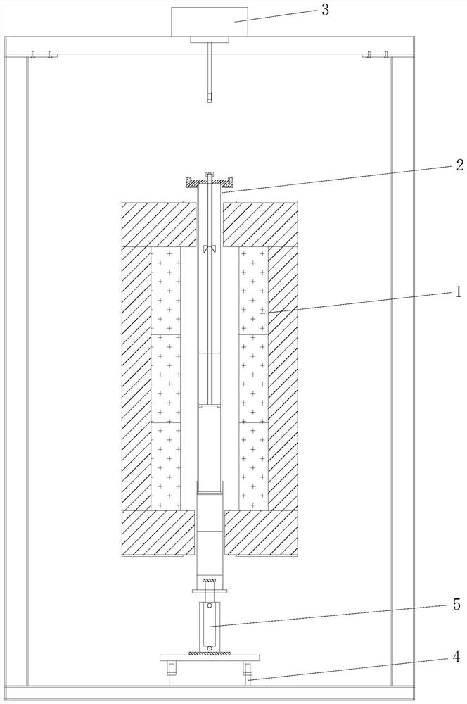
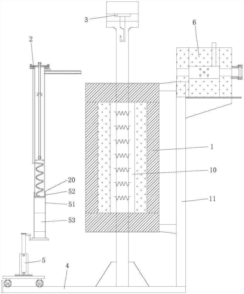
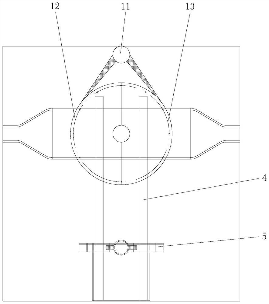
[0032] like Figure 1 to Figure 4 As shown, the reduction furnace of this embodiment includes a heating furnace 1, a reduction tank 2 and a hanging weighing device 3. The heating furnace 1 has a furnace 10 that can be opened and closed, and the hanging weighing device 3 is fixedly arranged on the furnace 10. The upper part is used to hang the reduction tank 2 in the furnace 10, and the reduction furnace also includes a function for moving the reduction tank 2 into the furnace 10 and hanging the reduction tank 2 on the hanging weighing device 3 and lifting the reduction tank 2 from the Take off on the hanging weighing device 3 and move out the loading and unloading tank device of the furnace 10. In this reduction furnace, a hanging weighing device 3 is fixed above the furnace 10 for hanging the reduction tank 2 in the furnace 10, and ...


PUM


Abstract

The invention discloses a reduction furnace. The reduction furnace comprises a heating furnace, a reduction tank and a hanging-type weighing device, wherein the heating furnace is provided with a hearth capable of being opened and closed; and the hanging-type weighing device is fixedly arranged above the hearth and used for hanging the reduction tank in the hearth. The reduction furnace further comprises a tank loading-unloading device used for moving the reduction tank into the hearth and hanging the reduction tank onto the hanging-type weighing device, and taking down the reduction tank fromthe hanging-type weighing device and moving the reduction tank out of the hearth. The reduction furnace has the advantages of being long in service life, high in treatment efficiency, high in weighing stability and accuracy, convenient to overhaul and maintain, and the like.

Description

technical field [0001] The invention relates to the technical field of heat treatment furnaces, in particular to a reduction furnace. Background technique [0002] The existing reduction furnace mainly includes a heating furnace, a cylindrical reduction tank, and a weighing balance. The upper part of the hearth of the heating furnace has an inlet and outlet for the reduction tank to pass through. The weighing balance is installed on the lifting end of the lifting device. In the reduction tank, hang the reduction tank on the weighing balance, and then hoist the reduction tank through the hoisting device to make the reduction tank move downward from the inlet and outlet on the top of the furnace into the furnace. The movement exits the furnace, then hoists and unloads to the unloading position and opens the reduction tank for unloading. This type of reduction furnace has disadvantages such as complicated operation, slow heat dissipation of the heating furnace, low efficiency,...

Claims


Application Information

Patent Timeline
IPC IPC(8): F27B17/00F27D1/00F27D5/00
CPCF27B17/0016F27D1/0043F27D5/0068F27D2005/0075
Inventor 李骞郭宇峰袁礼顺杨仕伟姜涛李光辉范晓慧杨永斌陈许玲张元波徐斌
Owner CENT SOUTH UNIV
Why Eureka
Try Eureka