Loading and unloading device for truck
A technology for unloading devices and trucks, which is applied in the field of loading and unloading devices for trucks. It can solve the problems of unsatisfactory loading and unloading requirements, troublesome loading and unloading, and limited use, and achieve the effects of convenient and labor-saving loading and unloading, fast loading and unloading, and strong adaptability
- Summary
- Abstract
- Description
- Claims
- Application Information
AI Technical Summary
Problems solved by technology
Method used
Image
Examples
Embodiment 1
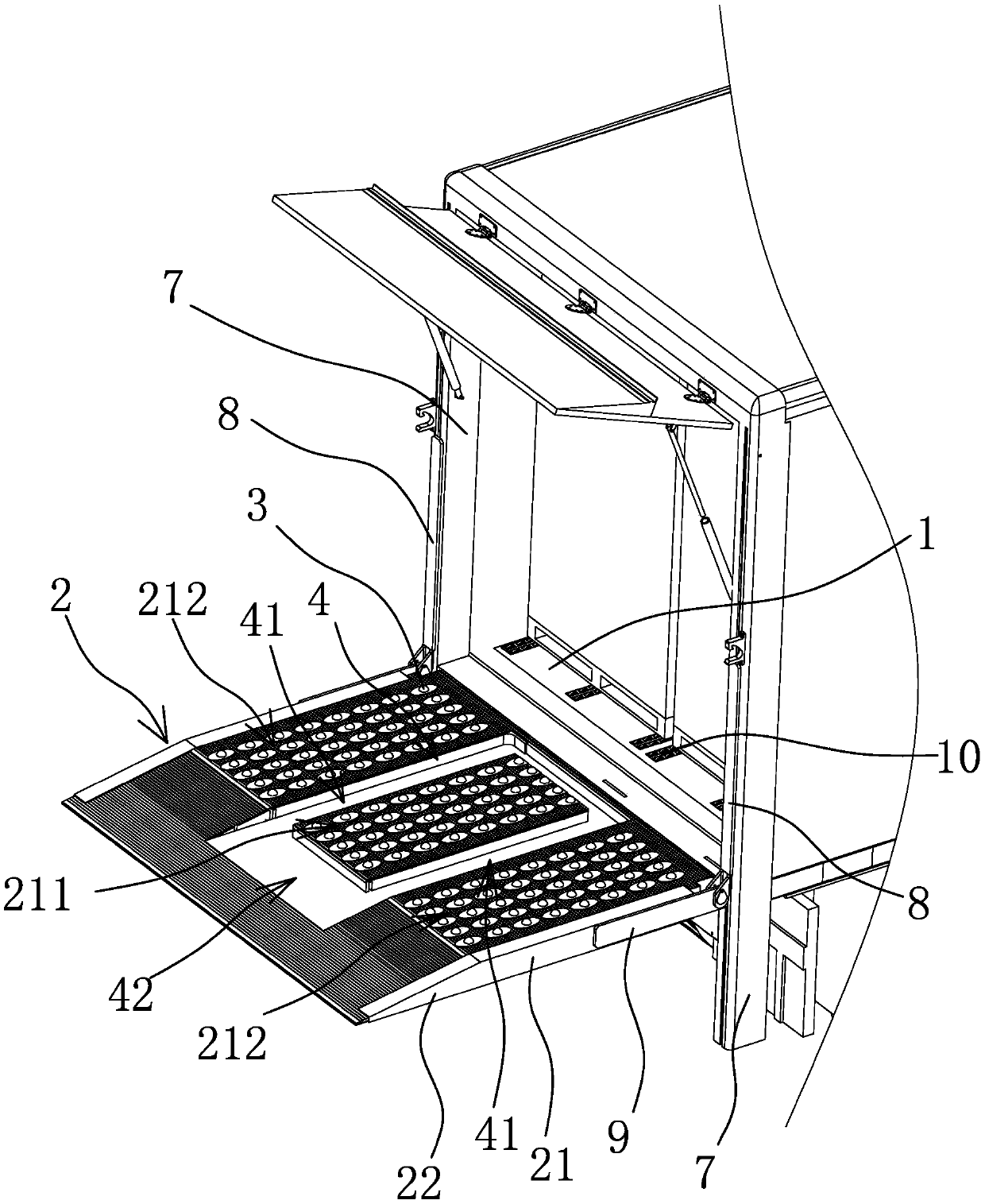
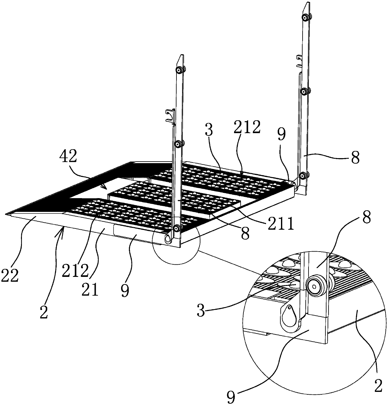
[0043] The loading and unloading device of the truck is mainly applied to a container truck, or can also be used for a truck without a container. Such as figure 1 As shown, the device includes a loading board 2 connected to the edge of the truck floor 1. In this embodiment, the loading board 2 is arranged at the tail of the truck. Of course, according to actual loading and unloading requirements, the loading board 2 can also be arranged on The side of the truck.
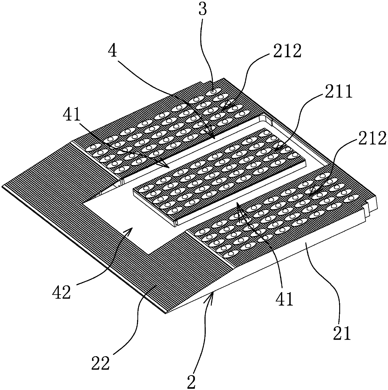
[0044] Such as figure 1 and figure 2 As shown, the upper surface of the loading board 2 is provided with a number of rolling parts 3 that can support the goods to move longitudinally and laterally on the loading board 2. In this embodiment, the rolling parts 3 are bull's-eye rollers. In the actual manufacturing process , and other rollers with universal rotation can also be used. The upper surface of the loading plate 2 is provided with a concave cavity 4 for the handling device to put in so that the goods can m...
Embodiment 2
[0052] Such as Figure 4 As shown, the loading and unloading device of the truck includes a loading plate 2 hinged at the edge of the truck floor 1, the structure of the loading plate 2, and the connection structure between the loading plate 2 and the truck are consistent with the first embodiment. Specifically, the loading board 2 includes a main board body 21 and a slope board 22. The loading board 2 can be expanded to a horizontal state and be flush with the truck floor 1. The rolling member 3 moving longitudinally and laterally is provided with a concave cavity 4 concave downward on the upper surface of the loading plate 2, and a trolley 5 for carrying goods and moving is arranged in the concave cavity 4, and the trolley 5 can Drive into or out of cavity 4.
[0053] Specifically, such as figure 2 As shown, the concave cavity 4 includes two straight grooves 41 located on the main body 21 and parallel to each other. Vertical, the two straight grooves 41 are all connected...
Embodiment 3
[0068] The structure and principle of this embodiment are basically the same as that of Embodiment 1, the difference is that: Figure 13 As shown, the loading board 2 is hinged at the edge of the truck floor 1, the loading board 2 can only swing, but cannot be lifted, and when the loading board 2 swings to a horizontal state, it is just flush with the truck floor 1. When unloading, the truck travels to a designated position, the loading plate 2 is opened to a horizontal state, and the supporting platform with a corresponding height supports the loading plate 2 .
PUM
 Abstract
Description
Claims
Application Information
 - R&D
- Intellectual Property
- Life Sciences
- Materials
- Tech Scout
- Unparalleled Data Quality
- Higher Quality Content
- 60% Fewer Hallucinations
Browse by: Latest US Patents, China's latest patents, Technical Efficacy Thesaurus, Application Domain, Technology Topic, Popular Technical Reports.
© 2025 PatSnap. All rights reserved.Legal|Privacy policy|Modern Slavery Act Transparency Statement|Sitemap|About US| Contact US: help@patsnap.com


