Valve train of internal combustion engine

A technology for valve trains and internal combustion engines, which is applied in the directions of machines/engines, connecting components, mechanical equipment, etc., and can solve problems such as complicated switching.

Inactive Publication Date: 2020-09-22
MAHLE INT GMBH
View PDF6 Cites 0 Cited by
  • Summary
  • Abstract
  • Description
  • Claims
  • Application Information

AI Technical Summary

Problems solved by technology

The spring biasing the catch element to the associated catch groove in the cylindrical area is maximally tensioned so that the cylindrical area lies between the catch grooves, which results in high friction in response to the adjustment, especially making switching by means of the X-groove complication
[0006] The high friction of the bolts in response to the adjustment displacement, the high installation space required and the resulting high costs are disadvantages of the known variable valvetrain systems

Method used


Image

  • Valve train of internal combustion engine
  • Valve train of internal combustion engine
  • Valve train of internal combustion engine

Examples


Embodiment Construction

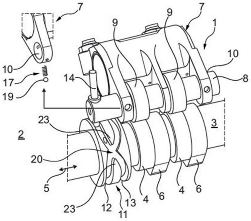
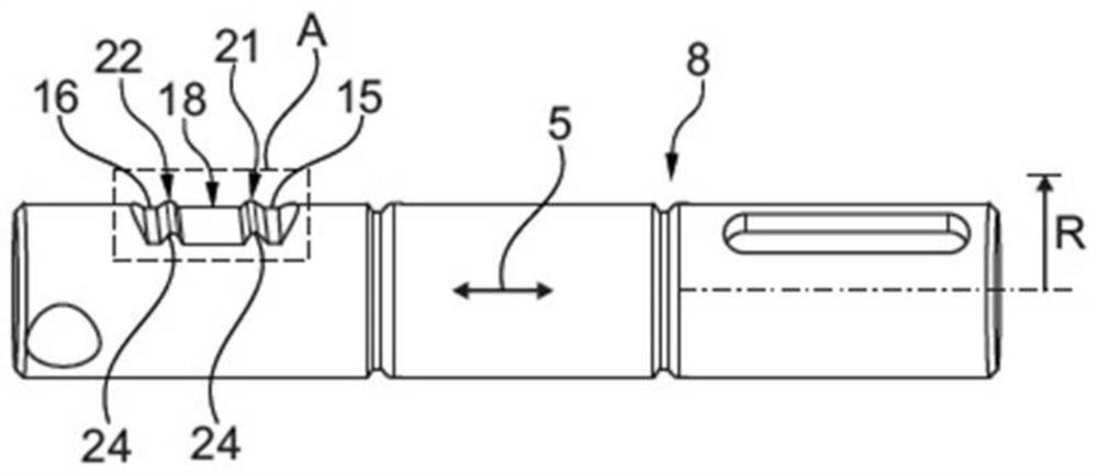
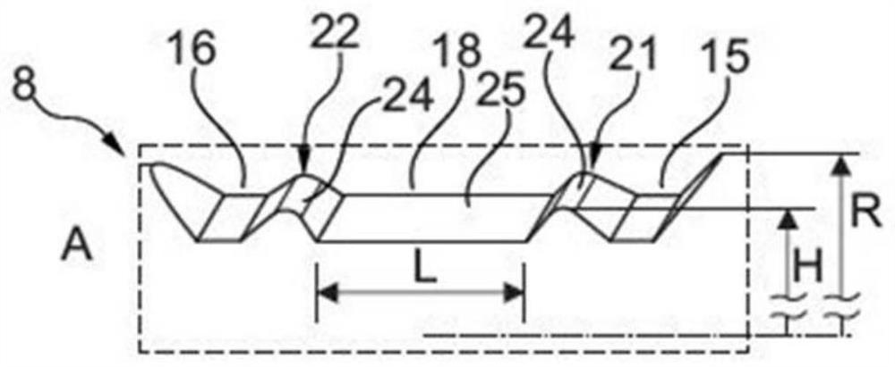
[0027] according to figure 1 According to the invention, a valve train 1 of an internal combustion engine 2 , not shown in detail, has a camshaft 3 comprising a first cam 4 and a second cam 6 adjacent to the first cam 4 in the axial direction 5 . A rocker arm assembly 7 is also provided which includes displacement bolts 8 (see also figure 2 and image 3 ), the displacement bolt 8 is adjustable in the axial direction 5 between at least two positions, and at least one cam roller 9, where two cam rollers 9 are mounted to the displacement bolt 8 in an axially fixed and rotatable manner. The displacement bolt 8 is thus mounted on the associated bearing lug 10 of the rocker arm assembly 7 . A guide profile 11 comprising a first guide track 12 and a second guide track 13 is arranged on the camshaft 3 . A switching pin 14 is additionally arranged in the displacement bolt 8, the switching pin 14 optionally engaging the first or the second guide rail 12, 13 (according to figure 1 T...


PUM


Abstract

The invention relates to a valve train of an internal combustion engine. The valve train of an internal combustion engine may include a camshaft (3), comprising first and second cams (6); a displacement bolt (8), which can be adjusted between at least two positions, at least one cam roller (9) being mounted on the displacement bolt (8)in an axially fixed and rotatable manner; a guide profile (11)comprising a first guide track (12) and a second guide track (13) intersecting each other in an intersection region (20); a switching pin (14) optionally engaging either the first or the second guiderail (12, 13), wherein in a first position the at least one cam roller (9) cooperates with the first cam (4) and in a second position it cooperates with the second cam (6); wherein a first catching groove (15) and a second catching groove (16) arranged axially adjacent thereto are provided on the displacement bolt (8); wherein a pre-biased capture element (19) is provided, which stabilizes the displacement bolt (8) in the first or second position and engages the third capture groove (18) in the intersection region (20). As a result, it is possible to create a valve train (1) with optimized installation space and reduced friction

Description

technical field [0001] The invention relates to a valvetrain of an internal combustion engine according to the preamble of claim 1, comprising a camshaft comprising a first cam and a second cam arranged axially adjacent thereto, and comprising Rocker arm assembly. Furthermore, the invention relates to displacement bolts for a valve train of this type. Background technique [0002] Common valve trains of internal combustion engines are known which have at least one first cam for the valve train on a camshaft and at least one second cam arranged adjacent thereto. Also provided is a rocker arm assembly comprising a displacement bolt capable of being adjusted in an axial direction between at least two positions and at least one cam roller mounted axially fixed and at the same time rotatable on the displacement bolt superior. The displacement bolt is thus mounted in the associated bearing lug of the rocker arm assembly, wherein the cam roller taps the cam profile of the first ...

Claims


Application Information

Patent Timeline
IPC IPC(8): F01L1/12F01L1/047F01L1/18F01L1/46F16B21/00F16B19/02
CPCF01L1/047F01L1/12F01L1/18F01L1/46F16B19/02F16B21/00F01L1/053F01L1/181F01L1/267F01L13/0036F01L2013/001F01L2301/00F01L2301/02F01L2305/00F01L1/0532F01L1/34416F01L13/0047F01L2001/0535F01L2013/0052F01L2305/02
Inventor 帕特里克·奥尔瑟托尔斯腾·伊内罗尔夫·科尔施耐尔马里奥·莫勒马库斯·瓦尔希
Owner MAHLE INT GMBH
Why Eureka
Try Eureka