
Cold crucible induction melting and die-casting device and method for preparing bulk amorphous material

A technology of induction smelting and cold crucible, applied in the field of metal smelting and casting, can solve the problems of hindering the die-casting process, uneven temperature, uneven shrinkage, etc., and achieve the effect of compact structure, good filling and low resistance

Active Publication Date: 2020-09-22
励德装备技术(宁波)有限公司
View PDF10 Cites 4 Cited by
  • Summary
  • Abstract
  • Description
  • Claims
  • Application Information

AI Technical Summary

Problems solved by technology

In these two technologies, the molten metal is injected into the barrel by its own weight, so there is a significant drop in temperature during the casting process, which has an adverse effect on the casting process: First, the molten metal cannot be completely filled into the mold, causing the casting to Second, part of the molten metal solidifies in the barrel, and these metal residues hinder the die-casting process of the next heat; third, the temperature of the molten metal decreases unevenly during the flow process, resulting in uneven shrinkage during the cooling process of the mold creating a gap

Method used


Image

  • Cold crucible induction melting and die-casting device and method for preparing bulk amorphous material
  • Cold crucible induction melting and die-casting device and method for preparing bulk amorphous material
  • Cold crucible induction melting and die-casting device and method for preparing bulk amorphous material

Examples


Embodiment Construction

[0052] Exemplary embodiments of the present disclosure will be described in more detail below with reference to the accompanying drawings. Although exemplary embodiments of the present disclosure are shown in the drawings, it should be understood that the present disclosure may be embodied in various forms and should not be limited by the embodiments set forth herein. Rather, these embodiments are provided for more thorough understanding of the present disclosure and to fully convey the scope of the present disclosure to those skilled in the art.

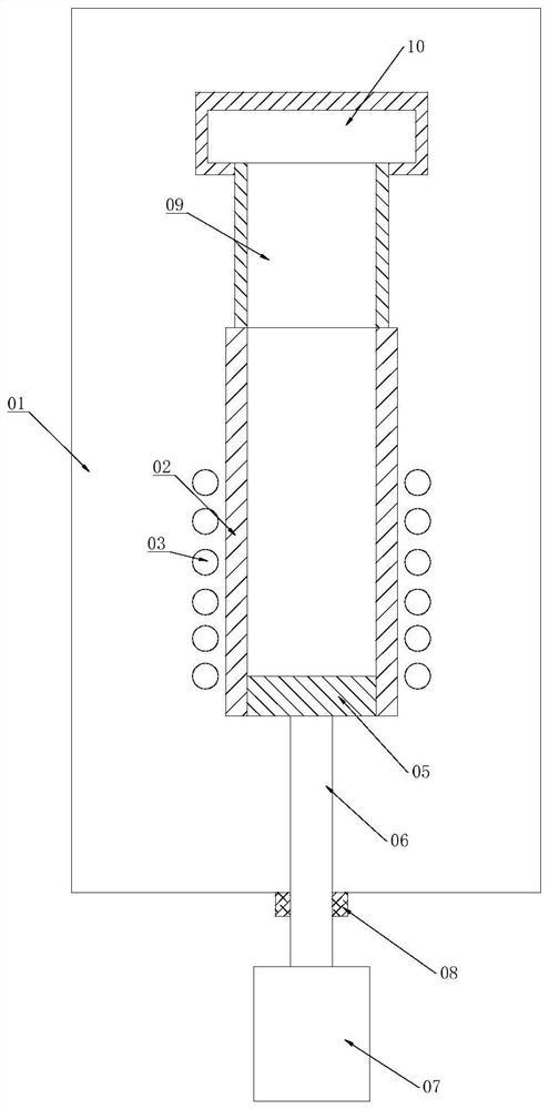
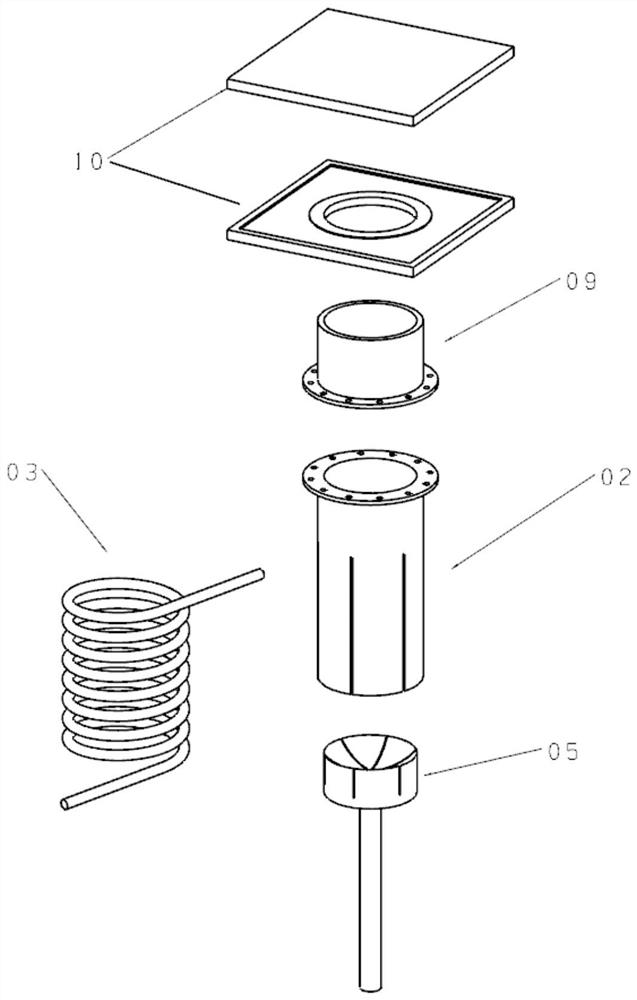
[0053] According to an embodiment of the present invention, a cold crucible induction melting-die casting device is proposed, such as figure 1 As shown, it includes: a vacuum melting chamber 01, a split-type water-cooled copper crucible 02 is fixedly arranged in the vacuum melting chamber 01, and the water-cooled copper crucible 02 is cylindrical (the water-cooled copper crucible has the same inner diameter along the axis ), both e...


PUM


Abstract

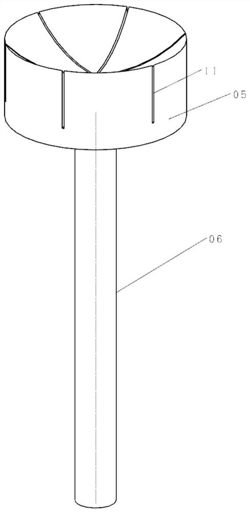
The invention discloses a cold crucible induction melting and die-casting device. The cold crucible induction melting and die-casting device comprises a vacuum melting chamber, and a water-cooled copper crucible is arranged in the vacuum melting chamber. An induction coil is wound on the outer wall of the water-cooled copper crucible, and a crucible bottom is arranged at the bottom of the water-cooled copper crucible. A push rod is arranged below the crucible bottom, penetrates through the bottom of the vacuum melting chamber through vacuum sealing and is combined with a driving mechanism. A gun barrel is arranged on the water-cooled copper crucible, and a mold chamber is arranged on the gun barrel. The invention further discloses a method for preparing a bulk amorphous material by using the device. The crucible, the gun barrel and the mold chamber are compactly combined without intervals. When the metal bulk amorphous material is prepared, the crucible bottom compulsively presses a metal melting tank into a mold, the liquid metal is short in stroke and small in resistance, so that the temperature drop is small, the flowability is high, the filling property is good, the quality andthe yield of castings are improved, the possibility of local solidification of molten metal in the gun barrel is reduced, the failure rate of blocking in the die casting process is reduced, and the service life of equipment and the production efficiency are improved.

Description

technical field [0001] The invention relates to a cold crucible induction smelting-die-casting device, and a method for preparing bulk amorphous materials by using the device, which is a technology for realizing pressure casting of metal bulk amorphous materials under cold crucible vacuum induction melting conditions, belonging to metal smelting and Technical field of casting. Background technique [0002] Amorphous metal materials have special properties that crystalline metal materials do not have, such as particularly high mechanical properties, electrical properties, or magnetic properties. Such materials have been developed for decades. On the basis of traditional amorphous materials, metal bulk amorphous materials have recently been developed, which is a material that can maintain an amorphous structure under the condition of a cross-sectional line size of several millimeters. The development of metal bulk amorphous materials has expanded the practical application fie...

Claims


Application Information

Patent Timeline
IPC IPC(8): C22C1/00C22C1/02C22C33/00C22C33/04B22D1/00B22D17/28
CPCC22C1/02C22C33/003C22C33/04B22D17/28B22D1/00C22C1/11
Inventor 李碚李佳李庚
Owner 励德装备技术(宁波)有限公司
Learn More