
Efficient sewage treatment system

A technology of sewage treatment system and sewage treatment tank, which is applied in water/sewage treatment, light water/sewage treatment, water/sewage treatment equipment, etc. Sewage treatment components clogging and other problems, to achieve the effect of reducing workload, scientific and reasonable structure, and reducing the possibility of clogging

Inactive Publication Date: 2020-09-22
唐晓晖
View PDF0 Cites 0 Cited by
  • Summary
  • Abstract
  • Description
  • Claims
  • Application Information

AI Technical Summary

Problems solved by technology

[0003] Before photocatalytic sewage treatment, it is often necessary to treat floating objects such as duckweed and plastic bags on the surface of sewage and large-particle pollutants, otherwise it will easily cause blockage of subsequent sewage treatment components, and the existing sewage treatment system floats The degree of mechanical automation of the cleaning part still needs to be improved
At the same time, in the actual application process of the photocatalytic sewage treatment equipment currently on the market, the sewage is treated only by covering the surface of the polluted water body with the graphene photocatalytic net, which leads to the inability of the lower sewage to effectively interact with the graphene photocatalytic net. At the same time, due to the need to use natural light in the photocatalytic process of sewage, the sewage treatment process is easily affected by the light intensity, which reduces the efficiency of sewage treatment

Method used


Image

  • Efficient sewage treatment system
  • Efficient sewage treatment system
  • Efficient sewage treatment system

Examples


Embodiment

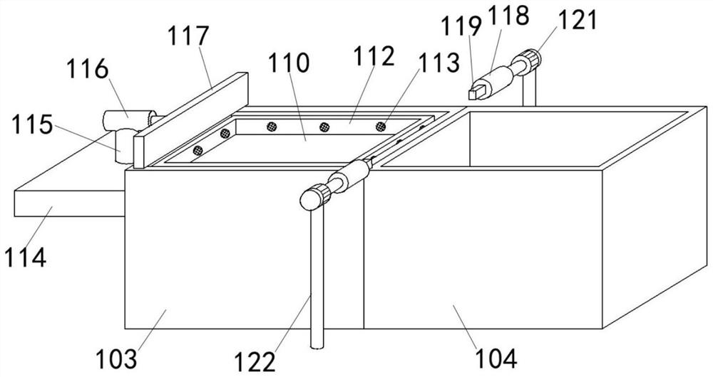
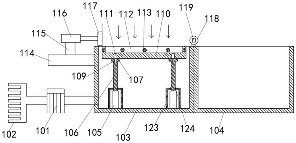
[0040] Example: such as Figure 1-5 As shown, a high-efficiency sewage treatment system includes a floating object cleaning device 100 and a visible light catalytic treatment device 200. After the floating object is cleaned by the floating object cleaning device 100, the sewage is sent to the visible light catalytic processing system by a booster pump 101 through each branch pipe 102. The sewage treatment tank 5 of the treatment device 200, the floating object cleaning device 100 includes a sewage transfer tank 103 and a floating object collection tank 104, at least two pneumatic cylinders 105 are fixedly connected to the bottom of the sewage transfer tank 103, and the output shaft 106 upper end of each pneumatic cylinder The contact plate 107 is fixed, and the contact plate 107 is provided with a positioning hole 109 for the insertion of the positioning shaft 108. The positioning shaft 108 is driven by the first electric telescopic rod 111 embedded in the collecting plate 110;...


PUM


Abstract

The invention discloses an efficient sewage treatment system. A floating object cleaning device comprises a sewage transfer pool and a floating object collecting pool, at least two pneumatic cylindersare fixedly connected to the bottom of the sewage transfer pool, the upper end of an output shaft of each pneumatic cylinder is fixedly connected to a contact disc, a positioning hole allowing a positioning shaft to be inserted is formed in each contact disc, and each positioning shaft is driven by a first electric telescopic rod fixedly embedded in a collecting disc; a surrounding plate is arranged on the periphery of the collecting disc, and a plurality of blocking nets are arranged on the surrounding plate; a mounting plate is fixedly connected to the side wall of the sewage transfer pool,a hydraulic cylinder is fixed to the mounting plate through a stand column, an output shaft of the hydraulic cylinder is fixedly connected to a push plate, a second electric telescopic rod is arranged on each of the two sides of the junction of the sewage transfer pool and the floating object collecting pool, the cross section of a rod body of the second electric telescopic rod is rectangular, arectangular inserting groove allowing the rod body of the second electric telescopic rod to be inserted therein is formed in the surrounding plate, the second electric telescopic rods are fixedly connected to output shafts of turnover motors, and the turnover motors are fixedly connected to the ground through fixing columns.

Description

technical field [0001] The invention relates to the technical field of sewage treatment, in particular to an efficient sewage treatment system. Background technique [0002] Sewage treatment is the process of purifying sewage to meet the water quality requirements of being discharged into a certain water body or reused. Sewage treatment is widely used in construction, agriculture, transportation, energy, petrochemical, environmental protection, urban landscape, medical treatment, catering, etc. In various fields, more and more people have entered the daily life of ordinary people. With the continuous development of science and technology, photocatalytic sewage treatment technology has gradually become popular, and photocatalytic sewage treatment equipment needs to be used in the process of sewage photocatalytic treatment; [0003] Before photocatalytic sewage treatment, it is often necessary to treat floating objects such as duckweed and plastic bags on the surface of sewage...

Claims


Application Information

Patent Timeline
Patent Type & Authority Applications(China)
IPC IPC(8): C02F9/08
CPCC02F1/001C02F1/30C02F1/40C02F1/52C02F9/00C02F2201/002C02F2201/009C02F2301/066C02F2303/14C02F2305/10
Inventor 唐晓晖
Owner 唐晓晖
Learn More