Control device of vehicle cooling device
A cooling device and control device technology, which is applied in the direction of battery/fuel cell control devices, power devices, vehicle components, etc., can solve the problems of cooling performance reduction, charging capacity limitation, charging time extension, etc., and achieve the effect of improving cooling performance
- Summary
- Abstract
- Description
- Claims
- Application Information
AI Technical Summary
Problems solved by technology
Method used
Image
Examples
Embodiment 1
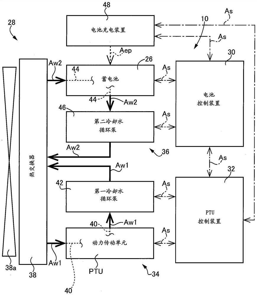
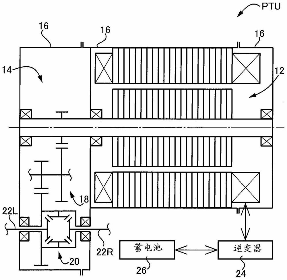
[0056] figure 1 It is a figure explaining the schematic structure of the electric vehicle 10 to which this invention is applied. in addition, figure 2 is the description set in figure 1 A schematic configuration diagram of a power transmission unit (drive unit) PTU of the electric vehicle 10 in FIG. It should be noted that the power transmission unit PTU is a drive unit that drives a pair of left and right drive wheels (not shown).
[0057] Such as figure 2 As shown, the power transmission unit PTU includes an electric motor 12 , a power transmission mechanism 14 and a housing case 16 . It should be noted that the electric motor 12 is a driving force source for traveling. In addition, the power transmission mechanism 14 transmits the driving force generated by the electric motor 12 to the above-mentioned pair of left and right drive wheels. In addition, the storage case 16 houses the electric motor 12 , the power transmission mechanism 14 , and the like. In addition, ...
Embodiment 2
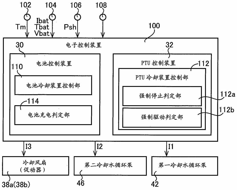
[0088] Figure 5 It is a figure explaining the electronic control unit (controller) of the cooling device 28 of another Example (Example 2) of this invention. The electronic control device of this embodiment is different from Embodiment 1 in that it is different from Embodiment 1 in that it is determined that one of the determination conditions that it is necessary to forcibly stop the PTU cooling device 34 is deleted in the forced stop determination unit 112a. The control device 100 is substantially the same. That is, even if it is determined by the battery charging determination unit 114 that the battery 26 is in a non-charging state, and the battery temperature Tbat [°C] of the battery 26 when it is determined that the battery 26 is in a non-charging state by the battery charging determination unit 114 is the third When the predetermined temperature Tbat3 [° C.] or higher is exceeded, the forced stop determination unit 112 a also determines that it is not necessary to forc...
Embodiment 3
[0093] Figure 6 It is a figure explaining the electronic control unit (controller) of the cooling device 28 of another Example (Example 3) of this invention. The electronic control device of the present embodiment differs in that the forced drive determination unit 112b is deleted, and is substantially the same as the electronic control device of the second embodiment in other respects.
[0094] Figure 6 This is a flowchart illustrating an example of a control operation of switching control for switching the drive state of the PTU cooling device 34 during parking, for example, in the electronic control device of the present embodiment. It should be noted, Figure 6 The S1 and S2 shown are with Figure 5 The contents of S1 and S2 shown are the same. Therefore, below, omit Figure 6 Description of S1 and S2 in.
[0095] In S23 corresponding to the function of the forced stop determination unit 112a, it is determined whether or not the remaining charge level SOC [%] of th...
PUM
 Abstract
Description
Claims
Application Information
 - R&D Engineer
- R&D Manager
- IP Professional
- Industry Leading Data Capabilities
- Powerful AI technology
- Patent DNA Extraction
Browse by: Latest US Patents, China's latest patents, Technical Efficacy Thesaurus, Application Domain, Technology Topic, Popular Technical Reports.
© 2024 PatSnap. All rights reserved.Legal|Privacy policy|Modern Slavery Act Transparency Statement|Sitemap|About US| Contact US: help@patsnap.com


