
Novel ball screw bearing disassembly device

A technology of bearing removal device and ball screw, which is applied in the direction of hand-held tools and manufacturing tools to achieve the effects of improving adaptability, avoiding surface loss and improving stability

Pending Publication Date: 2020-09-22
TEDERIC MACHINERY
View PDF0 Cites 0 Cited by
  • Summary
  • Abstract
  • Description
  • Claims
  • Application Information

AI Technical Summary

Problems solved by technology

[0003] Aiming at the problems existing in dismounting existing screw bearings, the present invention proposes a novel ball screw bearing dismounting device

Method used


Image

  • Novel ball screw bearing disassembly device
  • Novel ball screw bearing disassembly device

Examples


Embodiment Construction

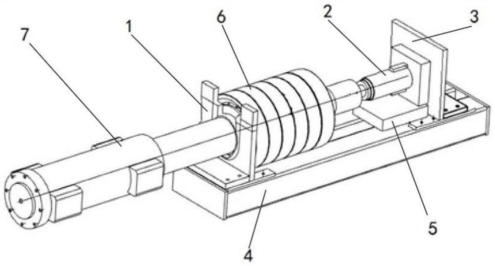
[0022] figure 1 Shown is a new type of ball screw bearing removal device according to the present invention, which includes a tooling base 4 , a front bracket 1 , a rear bracket 3 , an ejection assembly 2 and a backing plate 5 . Lead screw 7 bearing 6 is removed using this device.

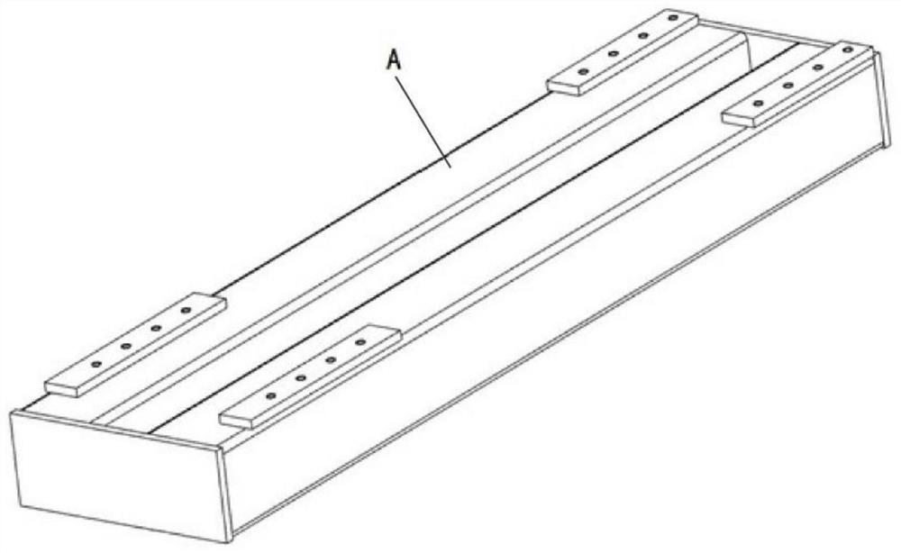
[0023] In this embodiment, the tooling base 4 is a sheet metal part provided with a hollow groove, and the surface A is provided with a plurality of threaded holes at different positions, such as figure 2 shown. The front bracket 1 is provided with a U-shaped groove, and the rear bracket 3 has welded ribs on the back. Both the front bracket 1 and the rear bracket 3 are installed on the tooling base 4 by threaded fasteners according to the size of the lead screw. The front support 1 is parallel to the rear support 3. The distance between the front bracket 1 and the rear bracket 3 can be adjusted through threaded holes fixed at different positions according to requirements.

[0024] Place the l...


PUM


Abstract

The invention provides a novel ball screw bearing disassembly device. The device mainly comprises a tool base, a front bracket, a rear bracket, an ejector assembly and backing plates. Both the front bracket and the rear bracket are connected with the tool base through threaded fasteners. The ejector assembly is placed between a lead screw and the rear bracket, and the ejector assembly is assistedby the backing plates to adjust the vertical position. The front bracket and the rear bracket are parallel to each other, and the distance between the front bracket and the rear bracket can be adjusted through threaded holes fixed at different positions according to requirements. The ejector assembly is placed vertically between the rear bracket and the lead screw, and the backing plates for adjusting the height of the ejector assembly are placed under the ejector assembly. According to the device, surface loss caused by knocking a bearing is avoided, the machining process is convenient, and machining efficiency is improved; a plurality of movable backing plates are designed, the requirements of different heights can be met through multi-layer stacking, and adaptability of the device is improved; a hollow slot is formed in the tool base, the design limits the radial movement of the lead screw in the device, and stability of the device is improved.

Description

technical field [0001] The invention relates to a novel ball screw bearing dismounting device, which belongs to the field of polymer material processing machinery. Background technique [0002] Lead screw is widely used in all electric injection molding machines, its function is to convert rotary motion into linear motion, and it also needs to transmit a certain amount of power. The quality of the lead screw directly affects the transmission efficiency, transmission accuracy and service life of the injection molding machine. Therefore, the all-electric injection molding machine has high requirements on the precision, strength and wear resistance of the screw. In the actual production process of the all-electric injection molding machine, it is inevitable that there will be bearing installation errors during the manual installation process, and the screw bearing needs to be manually disassembled. The traditional disassembly technology is manual disassembly, and the bearing ...

Claims


Application Information

Patent Timeline
Patent Type & Authority Applications(China)
IPC IPC(8): B25B27/06
CPCB25B27/06
Inventor 沈海波雷朗涛刘洋李旭光施重驹郑建国周宏伟章程徐方超
Owner TEDERIC MACHINERY
Learn More