Built-in rotor of surface concept permanent-magnet machine

A permanent magnet motor, surface technology, applied in the direction of magnetic circuit rotating parts, magnetic circuit shape/style/structure, etc., can solve the problems of complex structure permanent magnet shape, increased rotor cost, increased surface loss, etc., to avoid surface Loss, low processing cost, and the effect of improving reliability

Inactive Publication Date: 2008-02-13
SHANGHAI UNIV
View PDF2 Cites 0 Cited by
  • Summary
  • Abstract
  • Description
  • Claims
  • Application Information

AI Technical Summary

Problems solved by technology

The shape of the permanent magnet of this structure is complicated, the processing cost is large, and it leads to the increase of the cost of the rotor and the increase of the surface loss

Method used


Image

  • Built-in rotor of surface concept permanent-magnet machine
  • Built-in rotor of surface concept permanent-magnet machine

Examples


Embodiment Construction

[0027] The built-in rotor of the surface concept permanent magnet motor of the present invention will be further described in detail in conjunction with the accompanying drawings and a preferred implementation example:

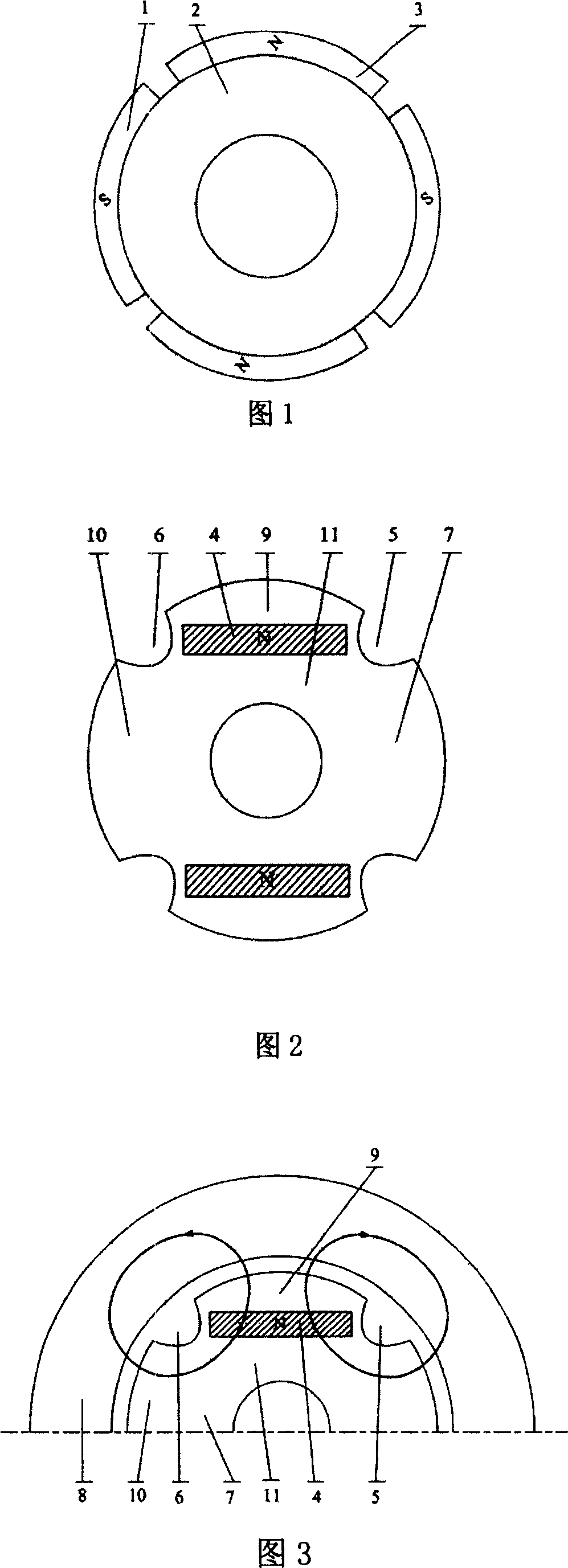
[0028] The surface-type rotor in the prior art is shown in FIG. 1 (taking a four-pole motor as an example), tile-shaped N poles 3 and S poles 1 are alternately placed on the surface of the rotor core 2 .

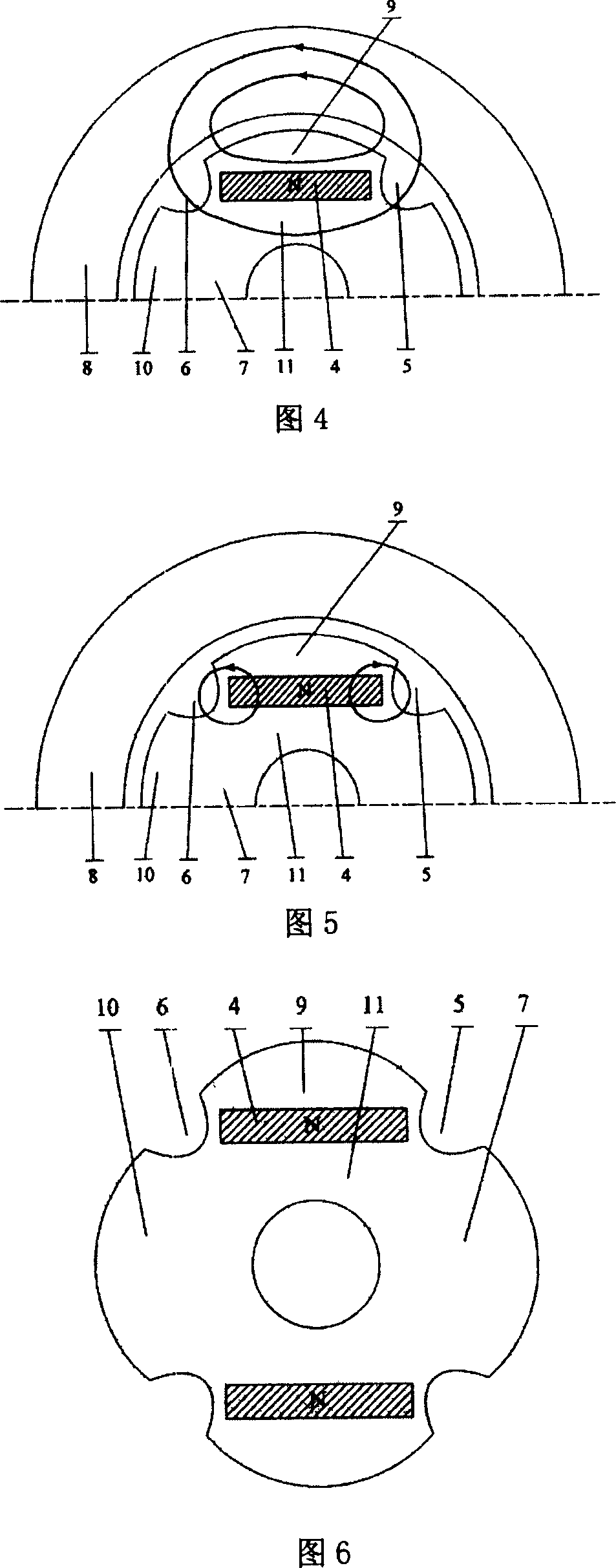
[0029] The built-in rotor of the surface concept permanent magnet motor of the present embodiment is as shown in Figure 2. Compared with the surface rotor structure, the number of permanent magnet blocks is reduced by half, the polarity is the same, and the shape is a regular rectangular permanent magnet 4 (N pole or S poles) are evenly distributed and embedded in the rotor core 7, and pits 5, 6 are set on both sides of each permanent magnet. The path of the direct-axis magnetic circuit is: Starting from the permanent magnet N pole 4, passing through the upp...


PUM


Abstract

This invention relates to a built-in rotor of a surface-type concept permanent magnet motor, which replaces two heteropolarity magnets for each pair pole of a general motor with a homopolarity and regular shaped magnet of each pair pole to be inserted in the rotor core, pits are set on the core surfaces of the rotors at both sides of the magnets, so that the d-axis and the quadrature have the same reactance to play the role of a magnet-isolation bridge.

Description

technical field [0001] The invention relates to a rotor of a permanent magnet motor, in particular to a built-in rotor of a surface concept permanent magnet motor. Background technique [0002] Exploring and selecting a reasonable rotor structure is one of the core issues in the design of permanent magnet motors. It is of great significance to the simplification of the manufacturing process, the reduction of production costs, and the optimization of the design of high-performance permanent magnet motors. There are various rotor structures of permanent magnet motors. As a whole, the most commonly used types are Surface Mounted Permanent Magnet (SPM) rotor structure and Interior Permanent Magne (IPM) rotor structure. [0003] The characteristic of the surface rotor structure is that the salient pole ratio ρ=L q / L d =1, no reluctance torque, large equivalent air gap, small armature response, good dynamic performance, and is often used in servo motors and traction motors. Su...

Claims


Application Information

Patent Timeline
Patent Type & Authority Patents(China)
IPC IPC(8): H02K1/27
Inventor 黄苏融张琪谢国栋
Owner SHANGHAI UNIV
Why Eureka
Try Eureka