Long-distance sub-wavelength grating structure applied to optical phased array transmitting unit

A subwavelength grating and optical phased array technology, applied in the field of optical phased array, can solve the problems of high manufacturing cost, high difficulty and cost, complex structure, etc., and achieve the effects of low cost, simple structure and low manufacturing difficulty

Pending Publication Date: 2020-09-18
HARBIN INST OF TECH SHENZHEN GRADUATE SCHOOL
View PDF6 Cites 9 Cited by
  • Summary
  • Abstract
  • Description
  • Claims
  • Application Information

AI Technical Summary

Problems solved by technology

[0005] The grating with a shallow etching depth will inevitably increase the manufacturing cost and complexity due to the periodic and small changes in the thickness of the waveguide; the thickness of the silicon nitride must be precisely controlled when the grating is made of silicon nitride; the grating structure and the waveguide are separated in the vertical direction The disadvantage is that its structure is complex, and the difficulty and cost of actual production are relatively high.
Generally speaking, the structure of these methods is more complicated, and there is higher difficulty in production, and the production cost is higher

Method used


Image

  • Long-distance sub-wavelength grating structure applied to optical phased array transmitting unit
  • Long-distance sub-wavelength grating structure applied to optical phased array transmitting unit
  • Long-distance sub-wavelength grating structure applied to optical phased array transmitting unit

Examples


Embodiment Construction

[0021] The present invention will be further described below in conjunction with the description of the drawings and specific embodiments.

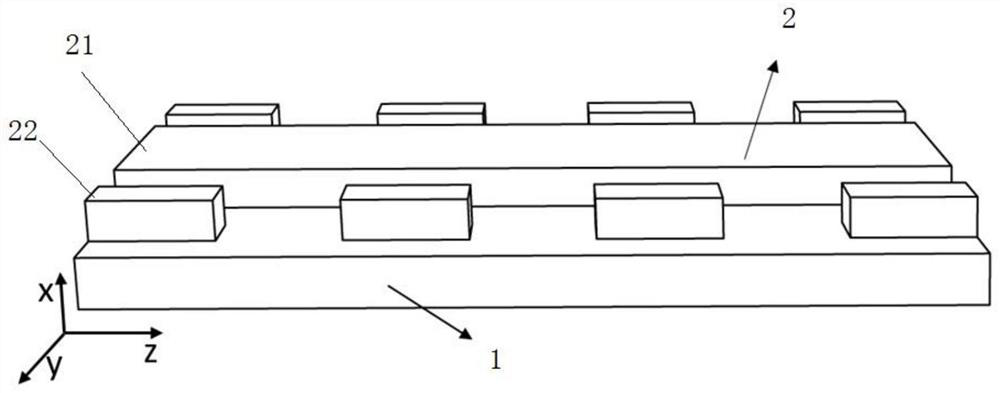
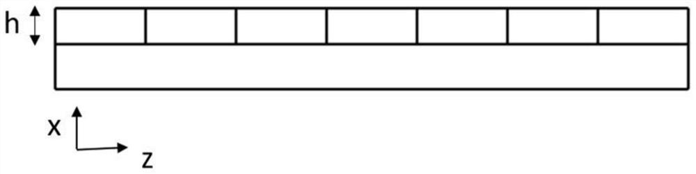
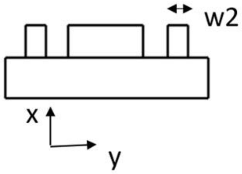
[0022] Such as Figure 1 to Figure 4 As shown, a long-distance sub-wavelength grating structure is used as a transmitting unit to realize a large-aperture optical phased array. The bottom layer is an oxide layer with a thickness of two microns, such as a silicon dioxide layer 1, and the upper layer is A sub-wavelength grating structure 2 of silicon material. The middle part of the structure is a straight waveguide 11 with a width of w1, and the sub-wavelength squares 2 with a width of W2 are periodically arranged along the direction of the waveguide at a distance d between both sides of the straight waveguide 11. The structure is etched on the SOI (Silicon on Insular) platform (not shown in the figure), first etching a layer of silicon dioxide layer 1, and then etching the silicon waveguide above the silicon dioxide layer 1, due to the c...


PUM

PropertyMeasurementUnit
widthaaaaaaaaaa
sizeaaaaaaaaaa

Abstract

The invention provides a long-distance sub-wavelength grating structure applied to an optical phased array transmitting unit. The structure comprises an upper-layer structure and a lower-layer structure which are arranged in an up-down stacked mode; the lower-layer structure is made of a material of which the refractive index is lower than that of the upper layer, such as various oxides; the upper-layer structure is a sub-wavelength grating structure made of materials such as silicon, silicon nitride, aluminum nitride, aluminum oxide and the like, and the refractive index of the materials is higher than that of the lower layer; the middle part of the upper-layer structure is a straight waveguide; sub-wavelength square blocks are arranged on two sides of the straight waveguide; and the sub-wavelength square blocks are arranged along the waveguide direction to form a grating. The long-distance sub-wavelength grating structure has the beneficial effects that the sub-wavelength grating waveguide is used for reducing the disturbance intensity of the grating to transmission light and increasing the effective length of the grating, so that the effective length of the grating is increased,and the far-field divergence angle of a light beam is reduced; the uniform emission of a near field can be controlled by controlling the position of the sub-wavelength square blocks; the structure issimple, the manufacturing difficulty is low, and the cost is low.

Description

technical field [0001] The invention relates to an optical phased array, in particular to a long-distance sub-wavelength grating structure that can be used in an optical phased array emitting unit. Background technique [0002] Beam steering and control technology has broad application prospects in many cutting-edge technology fields such as light detection and ranging, free space optical communication, and holographic display, and has received extensive attention in the past few decades. Designing an optical phased array with small far-field divergence angle, high beam energy efficiency, large scanning angle range, and high scanning speed has always been the goal pursued by people. [0003] The use of optical phased array for beam scanning has more flexible and faster beam control characteristics, and has the advantages of high resolution, high stability and high security. It can realize programmable beam steering control, non-inertial random pointing and multi-beam synchr...

Claims


Application Information

Patent Timeline
Patent Type & Authority Applications(China)
IPC IPC(8): G02F1/29
CPCG02F1/292G02B6/124G01S7/4814G02F1/2955
Inventor 徐小川陈佳欣李婉欣姚勇
Owner HARBIN INST OF TECH SHENZHEN GRADUATE SCHOOL
Why Eureka
Try Eureka