Two-dimensional spray field measurement method based on Mie scattering theory and Fraunhofer diffraction theory

A Mie scattering and measurement method technology, applied in the direction of measuring devices, particle and sedimentation analysis, instruments, etc., can solve the problems of complexity, droplet shedding, inaccuracy, etc., and achieve simple operation, reliable error measurement results, and high precision Effect

Active Publication Date: 2020-09-18
PLA PEOPLES LIBERATION ARMY OF CHINA STRATEGIC SUPPORT FORCE AEROSPACE ENG UNIV
View PDF23 Cites 2 Cited by
  • Summary
  • Abstract
  • Description
  • Claims
  • Application Information

AI Technical Summary

Problems solved by technology

However, the actual nozzle atomization process is far more complicated than the ideal situation. There are many ways to produce droplets. For example, the strong gas-liquid interaction can make the droplets directly peel off from the liquid film, and the huge turbulent kinetic energy inside the liquid film can make the droplets When the liquid film is broken and the liquid filament is formed, it will also generate accompanying droplets, etc.
However, because spraying at different positions has different particle size distributions, for example, inside the cone-shaped liquid film, there are often fewer droplets, while outside, the number of droplets is larger, and the particle size of these droplets is also significantly different. , it is inaccurate to use the average data to describe, which will cause a great impact on the follow-up research work, for example, it is impossible to predict the combustion area more accurately, it is difficult to better optimize the design of the injector, etc.
Therefore, it is difficult to measure the particle size distribution of the entire spray field only by the particle size distribution at the central axis, and there is an urgent need for a measurement method that can obtain the particle size of all droplets in the spray field

Method used

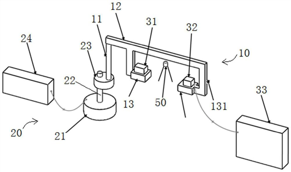
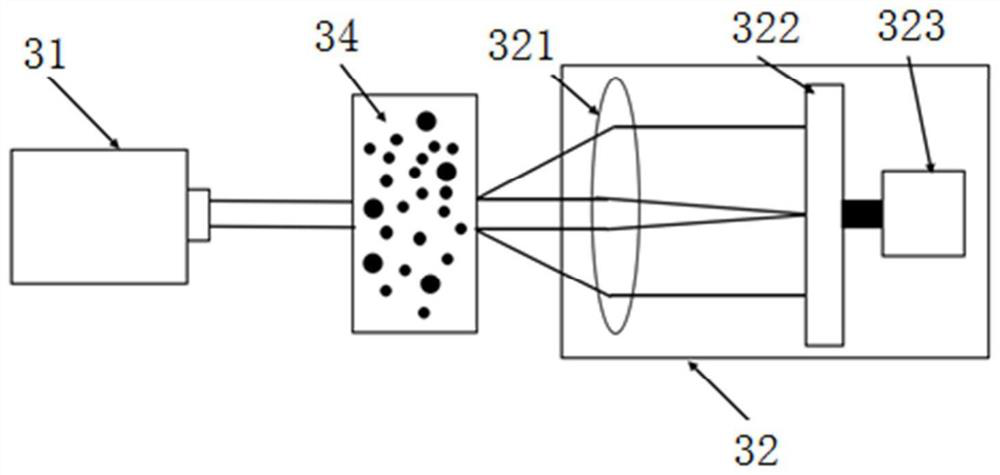
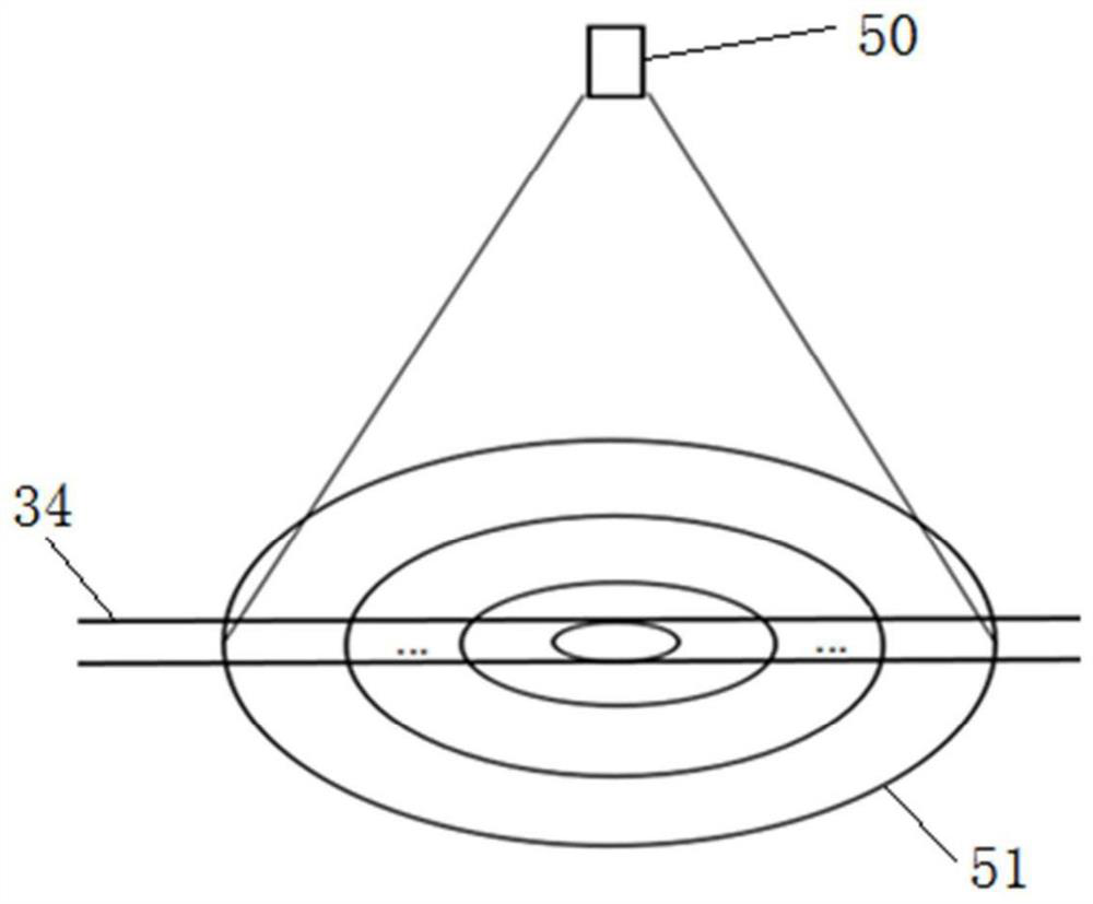

Image

  • Two-dimensional spray field measurement method based on Mie scattering theory and Fraunhofer diffraction theory
  • Two-dimensional spray field measurement method based on Mie scattering theory and Fraunhofer diffraction theory
  • Two-dimensional spray field measurement method based on Mie scattering theory and Fraunhofer diffraction theory

Examples


Embodiment Construction

[0067] The present invention will be further described in detail below in conjunction with the accompanying drawings and specific preferred embodiments.

[0068] In the description of the present invention, it should be understood that the orientations or positional relationships indicated by the terms "left side", "right side", "upper", "lower" are based on the orientations or positional relationships shown in the accompanying drawings, and are only For the purpose of describing the present invention and simplifying the description, rather than indicating or implying that the device or element referred to must have a specific orientation, be constructed and operate in a specific orientation, "first", "second" and the like do not represent components importance, and therefore should not be construed as limiting the invention. The specific dimensions used in this embodiment are only for illustrating the technical solution, and do not limit the protection scope of the present in...


PUM


Abstract

The invention discloses a two-dimensional spray field measurement method based on the Mie scattering theory and the Fraunhofer diffraction theory. The method comprises the steps of: 1, dividing a spray field, namely dividing the spray field into j equally-spaced circular rings in the radial direction, and enabling the distance between two adjacent circular rings to be D; 2, assuming particle sizedistribution of the spray field; 3, mounting a two-dimensional spraying field particle size distribution detection device; 4, calculating the set rotation angle of the support frame each time; 5, measuring the particle size distribution in a first circular ring; 6, measuring the particle size distribution in a second circular ring; 7, measuring the particle size distribution in an ith circular ring; 8, repeating the step 7 until the particle size distribution in a jth circular ring is measured; 9, measuring particle size distribution conditions in the spray field at different set angles; and 10, measuring the particle size distribution in the spray field under different spray elevations. By rotating a laser particle size analyzer, the particle size distribution of all liquid drops in a spray field is measured.

Description

technical field [0001] The invention relates to the detection problem of spray particle size distribution in the field of fuel atomization, in particular to a two-dimensional spray field measurement method based on Mie scattering theory and Fraunhofer diffraction theory. Background technique [0002] As human exploration of space activities increases year by year, the importance of space propulsion system technology becomes more and more obvious. Liquid rocket engines have attracted much attention in the development of human space technology due to their advantages such as high specific impulse, repeated start, multiple use, and adjustable thrust. Fuel atomization has become an important part of the development of liquid rocket engines. The function of the liquid rocket engine nozzle is to introduce the propellant into the combustion chamber at a certain flow rate, atomize it and mix it in a certain proportion to form a uniform mixture of fuel and oxidizer for gasification a...

Claims


Application Information

Patent Timeline
Patent Type & Authority Applications(China)
IPC IPC(8): G01N15/02
CPCG01N15/0205
Inventor 仝毅恒姜传金谢远李修乾苏凌宇林伟朱杨柱楚威任永杰赵家丰
Owner PLA PEOPLES LIBERATION ARMY OF CHINA STRATEGIC SUPPORT FORCE AEROSPACE ENG UNIV
Why Eureka
Try Eureka