


Quick Research
Generate reliable direction feasibility study reports for your R&D in just a few steps.

Technical Q&A
Discover and master advanced knowledge NOW. Basics, ideas, possibilities, all at once.

Find Solutions
As an expert in R&D theories, this can generate solutions to your technical problems instantly.

Evaluate Feasibility
Analyze your overall solution with one click, know your potential R&D risks in advance.

Monitor Landscape
Get weekly tech updates, stay abreast of the latest tech innovations and key insights.
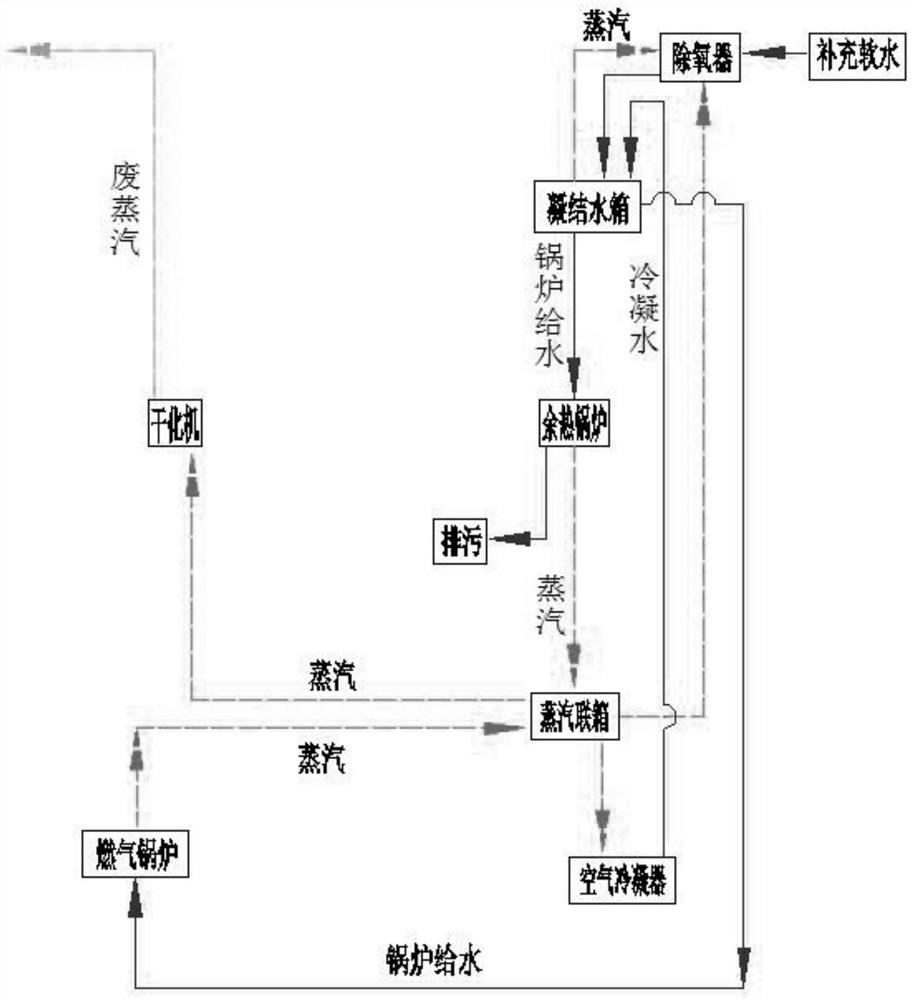
Thermal system for sludge incineration
A thermal system and sludge incineration technology, applied in the directions of preheating, incinerators, combustion methods, etc., can solve problems such as hidden dangers of boiler safety, oxygen corrosion of thermal system equipment and pipelines, cracked pipelines, etc., to improve stability and reliability. performance, continuous production capacity improvement, and the effect of increasing the diameter of the water inlet pipe
- Summary
- Abstract
- Description
- Claims
- Application Information
AI Technical Summary
Problems solved by technology
Method used
Image

Examples
Embodiment 1
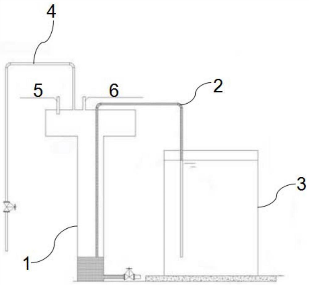
[0038] In this embodiment, a thermal system for sludge incineration is provided to modify the operation of the deaerator 7 in the thermal system. On the one hand, it is the modification of the problem of oxygen corrosion. The deaerator 7 is running under the design working condition. The two design working condition parameters of the deaerator 7, pressure and temperature, are a pair of related data, that is, the pressure cannot reach 20KPa, and the temperature must not reach 104°C. Therefore, as long as the pressure problem is solved, the can completely solve the problem.
[0039] In order to ensure that the pressure of the deaerator 7 is stable at 20KPa, the temperature is also stable at 104°C, as figure 2 As shown, the adopted scheme is as follows: including a water seal device, the water seal device is provided with a water seal chamber 1, the water seal chamber 1 is set as a T-shaped cavity, the water seal chamber 1 and the steam exhaust pipe of the deaerator 7 6, the st...
Embodiment 2
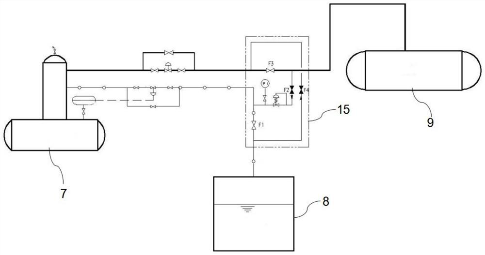
[0047] In the thermal system, the outlet of the deaerator 7 sends deoxygenated water to the condensate tank 8 through the feed water pump 10. Due to factors such as unreasonable location and small pipe diameter of the feed water pump 10, when the temperature of the deaerator 7 rises, Cavitation occurs in the feed water pump 10, and the deoxygenated water cannot be transported to the condensed water tank 8, resulting in frequent production shutdowns due to subsequent inability to replenish water.
[0048] On the basis of Example 1, in order to further improve the operational stability of the feed water pump 10 of the thermal system, to optimize the thermal system of sludge incineration, such as Figure 4 As shown, adopt the following technical scheme:
[0049] The outlet of the deaerator 7 is connected with a DN65 pipeline, and the DN65 pipeline is connected in parallel with 5 roads of water replenishment pipes, and each water replenishment pipe 5 is provided with a feedwater p...
Embodiment 3
[0052] The condensed water at the outlet of the air condenser 11 is low-temperature water, which cannot directly enter the pressurized condensed water tank 8. In order to make the air condenser 11 return water to the condensed water tank 8, it has a better energy-saving effect. On the basis of Example 2, in order to further improve the return water problem of the air condenser 11 of the thermal system, to optimize the thermal system of sludge incineration, such as Figure 5 , Image 6 As shown, adopt the following technical scheme:
[0053] Such as Figure 5 As shown, the steam header 9 is connected with an air condenser 11, the air condenser 11 is connected to the condensed water tank 8 through the return water pipeline, and the power drainage pump device 12 is arranged on the return water pipeline, and the return water is drained by the power drainage pump device 12. Return to the condensate tank 8 after pressurization, and the power drainage pump device 12 converts the in...
PUM
 Abstract
Description
Claims
Application Information
 - R&D Engineer
- R&D Manager
- IP Professional
- Industry Leading Data Capabilities
- Powerful AI technology
- Patent DNA Extraction
Browse by: Latest US Patents, China's latest patents, Technical Efficacy Thesaurus, Application Domain, Technology Topic, Popular Technical Reports.
© 2024 PatSnap. All rights reserved.Legal|Privacy policy|Modern Slavery Act Transparency Statement|Sitemap|About US| Contact US: help@patsnap.com