Radio communication terminal and transmission power control method
A technology for transmission power control and wireless communication terminals, which is applied in wireless communication, power management, and device selection, etc. It can solve problems such as inability to communicate with other terminal devices in the surrounding area, shortened battery life, and increased interference from other terminal devices in the surrounding area.
- Summary
- Abstract
- Description
- Claims
- Application Information
AI Technical Summary
Problems solved by technology
Method used
Image
Examples
Embodiment 1
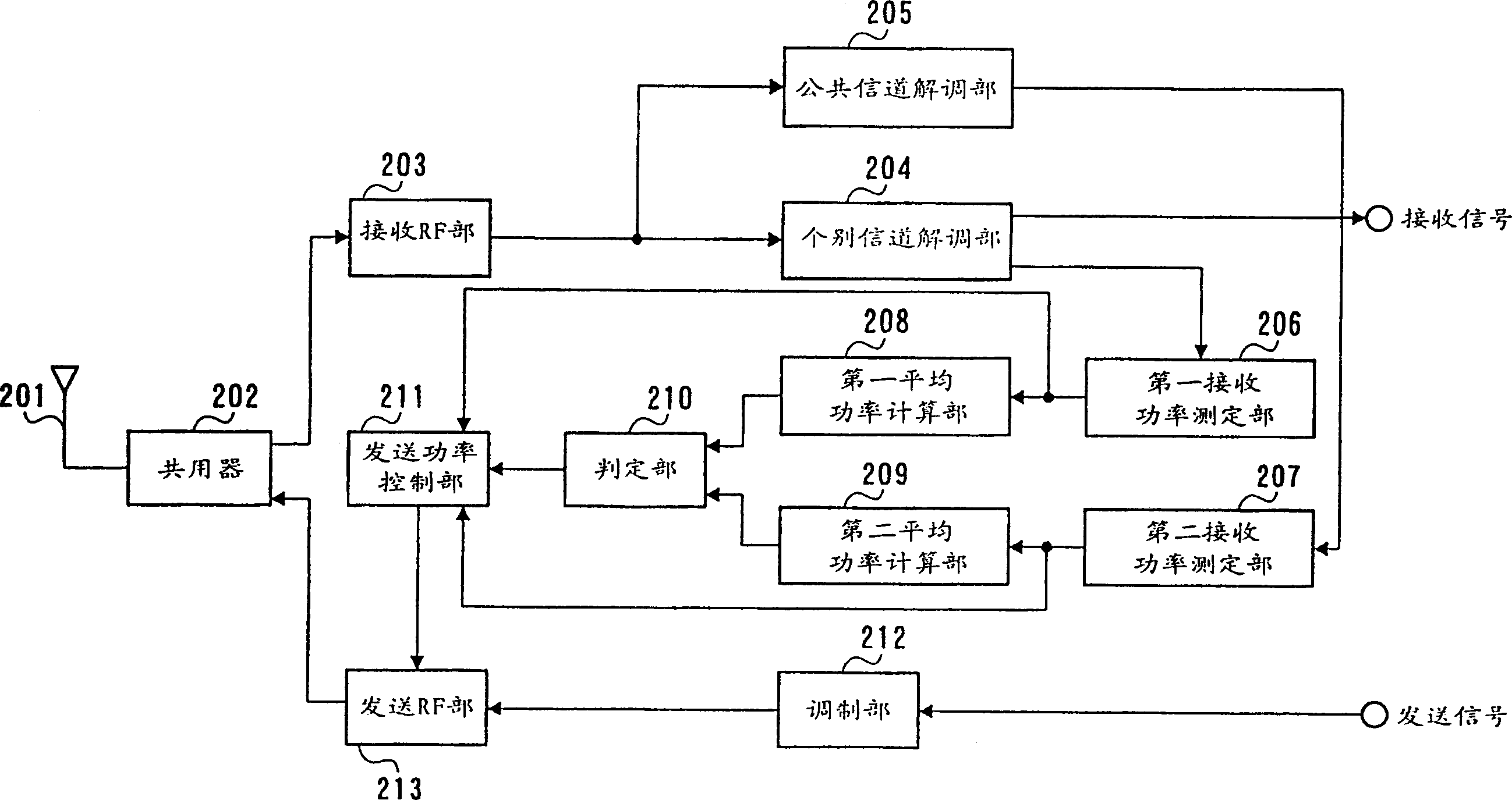
[0035] image 3 It is a block diagram showing the structure of the terminal device of the first embodiment.
[0036] The duplexer 202 switches the signal path between transmission and reception, outputs the signal received from the antenna 201 to the reception RF unit 203 , and outputs the transmission signal output from the transmission RF unit 213 to the antenna 201 .
[0037] The receiving RF unit 203 amplifies the received power, converts the frequency of the received signal, and outputs a baseband signal. The dedicated channel demodulation unit 204 despreads and demodulates the baseband signal using the dedicated channel spreading code, and extracts the signal of the dedicated channel of the own station. The common channel demodulation unit 205 despreads the baseband signal using the common channel spreading code.
[0038] The first received power measurement unit 206 measures the received power RMD(t1) of the despread dedicated channel. The second received power measu...
Embodiment 2
[0063] Embodiment 2 is an embodiment in which the transmission gain is corrected based on the average received power of the common channel and the average received power of the individual channels when the directivity of the individual channels varies.
[0064] Since the structure of the terminal device in Embodiment 2 is the same as figure 2 The same as shown, so its description is omitted.
[0065] When it is determined that there is a directivity deviation, the transmission power control unit 211 increases the gain GM(t2 ) is set to a value obtained by subtracting the difference between the average received power ARMC(t1) of the common channel and the average received power ARMD(t1) of the individual channel from the threshold value C.
[0066] GM(t2)=G0-RMD(t1)-(C-(ARMC(t1)-ARMD(t1)))
[0067] (7)
[0068] Below, use Figure 5 The flow chart shown is for explaining the flow of transmission power control of the terminal device in the second embodiment.
[0069] First,...
Embodiment 3
[0075] Embodiment 3 is an embodiment in which the transmission gain is calculated from the received power of the common channel when the directivity of individual channels varies.
[0076] Since the structure of the terminal device in Embodiment 3 is the same as figure 2 The same as shown, so its description is omitted.
[0077] When it is determined that there is a directivity deviation, the transmission power control unit 211 uses the fixed gain G0 and the measured received power RMC(t1) of the common channel to perform Formula to control the gain GM (t2) of the sending amplifier.
[0078] GM(t2)=G0-RMC(t1) (8)
[0079] Below, use Figure 6 The flow chart shown is for explaining the flow of transmission power control of the terminal device in the third embodiment.
[0080] First, in the first received power measuring section 206, the received power of the despread dedicated channel of the own station is measured (ST501), and in the same way, in the second received power...
PUM
 Abstract
Description
Claims
Application Information
 - R&D
- Intellectual Property
- Life Sciences
- Materials
- Tech Scout
- Unparalleled Data Quality
- Higher Quality Content
- 60% Fewer Hallucinations
Browse by: Latest US Patents, China's latest patents, Technical Efficacy Thesaurus, Application Domain, Technology Topic, Popular Technical Reports.
© 2025 PatSnap. All rights reserved.Legal|Privacy policy|Modern Slavery Act Transparency Statement|Sitemap|About US| Contact US: help@patsnap.com


