
Drilling and cutting device for stainless steel product machining

A cutting device, stainless steel technology, applied in the direction of feeding devices, manufacturing tools, metal processing equipment, etc., can solve the problems of large space occupation, single cutting or drilling function of the device, high cost, etc., to improve stability and reliability, improve The effect of processing efficiency and processing quality, flexible and convenient operation control

Inactive Publication Date: 2020-09-18
SUZHOU SAISHUOLA STAINLESS STEEL PROD CO LTD
View PDF0 Cites 1 Cited by
  • Summary
  • Abstract
  • Description
  • Claims
  • Application Information

AI Technical Summary

Problems solved by technology

[0003] When processing stainless steel products, drilling and cutting devices are needed, but the existing devices generally only have a single cutting or drilling function, and devices that integrate drilling and cutting functions are generally expensive and occupy a large space. more inconvenient

Method used


Image

  • Drilling and cutting device for stainless steel product machining
  • Drilling and cutting device for stainless steel product machining
  • Drilling and cutting device for stainless steel product machining

Examples


Embodiment 1

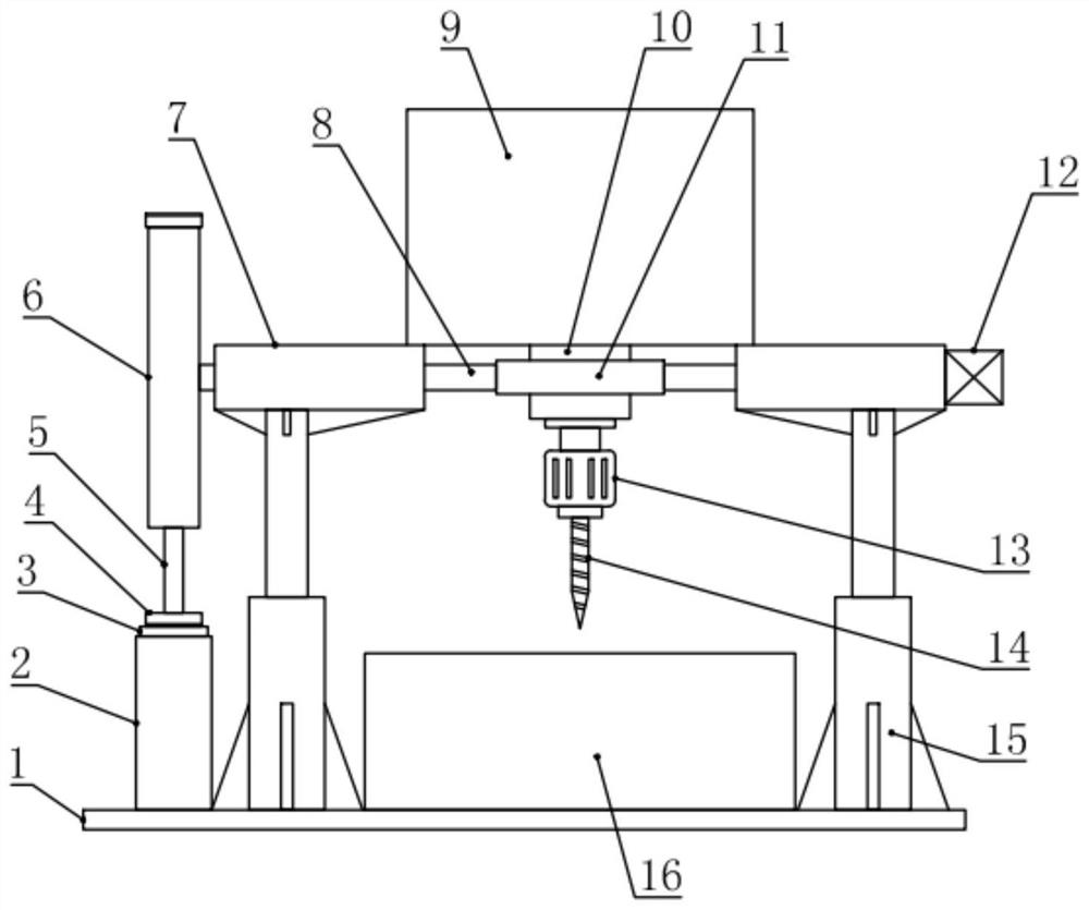
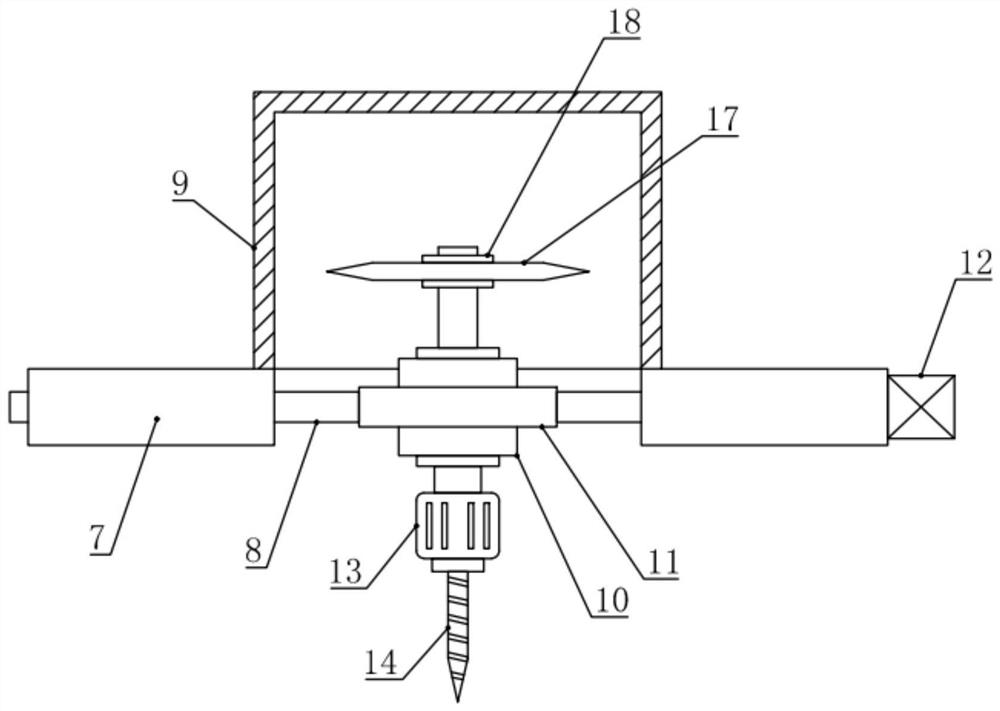
[0018] see Figure 1-2 , in an embodiment of the present invention, a drilling and cutting device for processing stainless steel products includes a base 1, a support base 2 and a processing table 16, the support base 2 and the processing table 16 are installed and fixed on the base 1, and the processing table The top of 16 is also fixed with a rotating support assembly through a plurality of telescopic cylinders 15. The middle part of the rotating support assembly is fixed with a double-axis extension motor 10, and the output shafts on both sides of the double-axis extension motor 10 are respectively detachably equipped with drill bits. 14 and a cutting wheel 17, one end of the rotating support assembly is also equipped with an overturning motor 12 for driving the biaxial extension motor 10 to perform 180° flipping, and the other end of the rotating support assembly is also installed with a motor for turning the biaxial extension The motor 10 is a positioning assembly for pos...

Embodiment 2

[0021] see Figure 1-4 , the difference between this embodiment and embodiment 1 is:

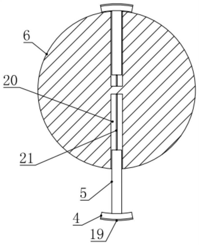
[0022] In this example, if figure 1 , 2 As shown in and 4, the rotating support assembly includes a support cylinder 7, a support shaft 8 and a motor fixing ring seat 11, two of the support cylinders 7 are arranged horizontally, and a The supporting shaft 8, the opposite ends of the two supporting shafts 8 are installed and fixed with a motor fixing ring seat 11, and the biaxial extension motor 10 is installed and fixed on the motor fixing ring seat 11; the lower sides of the two supporting cylinders 7 A telescopic cylinder 15 is respectively installed and fixed, and the lower end of the telescopic cylinder 15 is fixed on the base 1. Through the cooperation of the support shaft 8 and the motor fixing ring seat 11, the biaxial extension motor 10 can be stably rotated and supported, and the telescopic cylinder 15 can drive the rotational support Components move up and down.

[0023] Furthe...


PUM


Abstract

The invention relates to the field of stainless steel product machining, in particular to a drilling and cutting device for stainless steel product machining. The device comprises a base, a supportingseat and a machining table, the supporting seat and the machining table are arranged and fixed on the base, a rotary supporting assembly is fixed above the machining table through multiple telescopiccylinder frames, a double-shaft-extension motor is fixedly arranged in the middle of the rotary supporting assembly, a drill bit and a cutting wheel are detachably arranged on output shafts on the two sides of the double-shaft-extension motor, a turning over motor used for driving the double-shaft-extension motor to be turned over by 180 degrees is arranged at one end of the rotary supporting assembly, and the other end of the rotary supporting assembly is provided with a positioning assembly used for positioning the double-shaft-extension motor after the double-shaft-extension motor is turned over. According to the device, drilling or cutting machining on a stainless steel products is facilitated, the operation and control are flexible and convenient, and the machining efficiency and themachining quality are improved.

Description

technical field [0001] The invention relates to the field of stainless steel product processing, in particular to a drilling and cutting device for stainless steel product processing. Background technique [0002] Because stainless steel products have the characteristics of smooth and firm surface, not easy to accumulate dirt, and easy to clean, they are widely used in building materials decoration, food processing, catering, brewing and chemical industries. [0003] When processing stainless steel products, drilling and cutting devices are needed, but the existing devices generally only have a single cutting or drilling function, and devices that integrate drilling and cutting functions are generally expensive and occupy a large space. more inconvenient. [0004] Therefore, in view of the above present situation, there is an urgent need to develop a drilling and cutting device for processing stainless steel products to overcome the deficiencies in current practical applica...

Claims


Application Information

Patent Timeline
IPC IPC(8): B23P23/02B23Q1/26B23Q5/34
CPCB23P23/02B23Q1/26B23Q5/34
Inventor 史忠平
Owner SUZHOU SAISHUOLA STAINLESS STEEL PROD CO LTD
Learn More