Remote wireless charging receiving end and transmitting end

A wireless charging and receiving end technology, applied in antennas, electrical components, circuit devices, etc., can solve problems such as loss, usage scenarios, dependence on weather conditions, and high costs

Pending Publication Date: 2020-09-15
BEIJING INVISPOWER TECH CO LTD
View PDF1 Cites 0 Cited by
  • Summary
  • Abstract
  • Description
  • Claims
  • Application Information

AI Technical Summary

Problems solved by technology

The patent uses solar collectors for "photoelectric conversion", but a large part of the solar spectrum provides energy far greater than the band gap energy of commonly used semiconductor materials, and most of the energy, especially in the infrared band, is converted into heat due to lattice vibrations is lost, and multi-junction tandem solar cells that overcome this limitation offer slightly higher efficiencies in the visible band, but at a high cost
Moreover, this kind of solar charging equipment is dependent on the use scene and weather conditions. Indoor, night and other scenes, for solar charging, it is powerless.

Method used


Image

  • Remote wireless charging receiving end and transmitting end
  • Remote wireless charging receiving end and transmitting end
  • Remote wireless charging receiving end and transmitting end

Examples


Embodiment Construction

[0022] Embodiments of the present invention are described in detail below, examples of which are shown in the drawings, wherein the same or similar reference numerals designate the same or similar elements or elements having the same or similar functions throughout. The embodiments described below by referring to the figures are exemplary only for explaining the present invention and should not be construed as limiting the present invention.

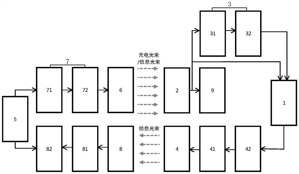
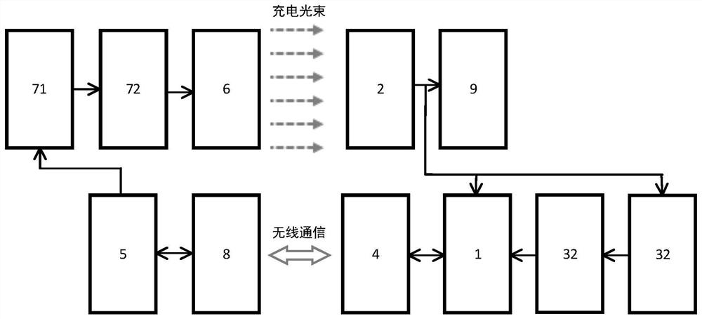
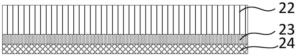
[0023] The invention discloses a receiving end of long-distance wireless charging (hereinafter referred to as the receiving end). Generally, when performing wireless charging, it is necessary to cooperate with the receiving end and the transmitting end of wireless charging (hereinafter referred to as the transmitting end), and the combination of the two can form a Long-distance wireless charging system. Wireless charging may also be referred to as wireless energy transfer.

[0024] First, the receiving end will be described. combine f...


PUM


Abstract

The invention discloses a remote wireless charging receiving end and transmitting end. The receiving end comprises a receiving end control system, a receiving antenna and a receiving end processor, wherein the receiving antenna is respectively communicated with the receiving end control system, the receiving end processor and a load; the receiving end processor is communicated between the receiving antenna and the receiving end control system; and the receiving antenna is composed of a plurality of optical antennas. According to the remote wireless charging receiving end and transmitting end,wireless transmission of electric energy can be achieved, the remote wireless charging function can be achieved through light energy, and meanwhile, the remote wireless charging receiving end and transmitting end are not affected by the environment such as night and cloudy days.

Description

technical field [0001] The invention relates to the field of wireless charging, in particular to a receiving end and a transmitting end of long-distance wireless charging. Background technique [0002] Long-distance wireless charging is wireless charging in the true sense in people's minds. For example, the patent with the publication number CN110525243A discloses a wireless charging device for drones. machine for wireless charging. The patent uses solar collectors for "photoelectric conversion", but a large part of the solar spectrum provides energy far greater than the band gap energy of commonly used semiconductor materials, and most of the energy, especially in the infrared band, is converted into heat due to lattice vibrations Multi-junction tandem solar cells that overcome this limitation offer slightly higher efficiencies in the visible band, but at a high cost. Moreover, this kind of solar charging equipment is dependent on usage scenarios and weather conditions. I...

Claims


Application Information

Patent Timeline
Patent Type & Authority Applications(China)
IPC IPC(8): H02J50/30H02J50/80H01Q1/38H01Q1/24H01Q23/00
CPCH01Q1/24H01Q1/38H01Q23/00H02J50/30H02J50/80
Inventor 王哲陆钧贺凡波葛俊杰马俊超
Owner BEIJING INVISPOWER TECH CO LTD
Why Eureka
Try Eureka