
Electronic execution unit working state self-holding protection circuit and system

A technology of working status and electronic execution, which is applied in general control systems, control/regulation systems, instruments, etc., and can solve problems such as inability to solve microcontroller output signal protection, failure, and unsuitability for new energy vehicle control systems

Active Publication Date: 2020-09-15
智新控制系统有限公司
View PDF7 Cites 0 Cited by
  • Summary
  • Abstract
  • Description
  • Claims
  • Application Information

AI Technical Summary

Problems solved by technology

Although the structure is simple, its stability is poor. Once there is a problem with the time domain signal, the device will fail
Not suitable for complex control systems of new energy vehicles
[0004] CN105553079A A power-down protection device for a new energy vehicle controller and a new energy vehicle, it only realizes the power-down protection of the vehicle, and cannot solve the protection when the output signal of the microcontroller is abnormal
[0005] In the past vehicle-mounted control circuits, some types of microcontrollers may send out unstable state signals when initializing (such as figure 1 above picture)

Method used


Image

  • Electronic execution unit working state self-holding protection circuit and system
  • Electronic execution unit working state self-holding protection circuit and system
  • Electronic execution unit working state self-holding protection circuit and system

Examples


Embodiment Construction

[0028] The following specific embodiments are used to explain the technical solutions of the claims of the present invention, so that those skilled in the art can understand the claims. The protection scope of the present invention is not limited to the following specific implementation structures. Those skilled in the art that include the technical solutions of the claims of the present invention and are different from the following specific embodiments are also within the protection scope of the present invention.

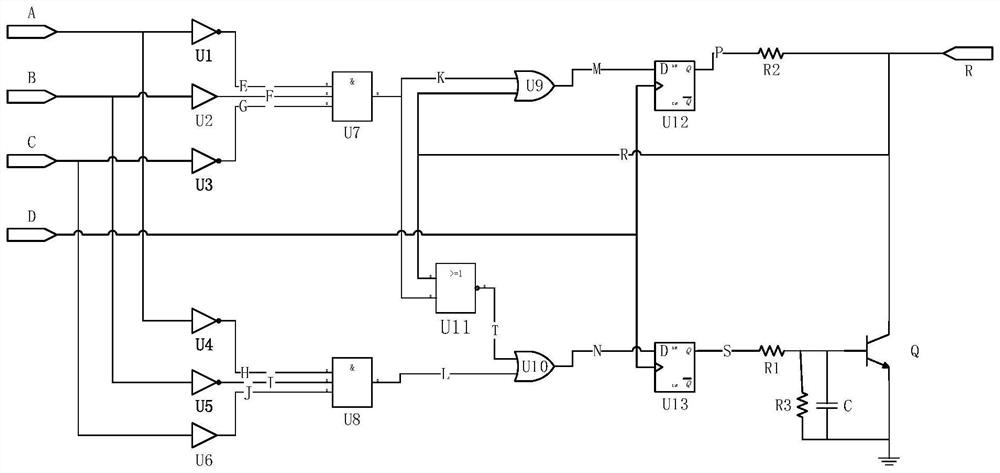
[0029] Such as figure 2 As shown, in this embodiment, the logic signal input terminals are three logic signals A, B, C; the first logic circuit includes a first group of two NOT circuits U1, U3 and a signal connected to the logic input signal. Buffer U2; the output of the two NOT circuits and the signal buffer is connected to the first three-input AND circuit U7; the output signal of the AND circuit U7 is K.

[0030] The second logic circuit includes a second group ...


PUM


Abstract

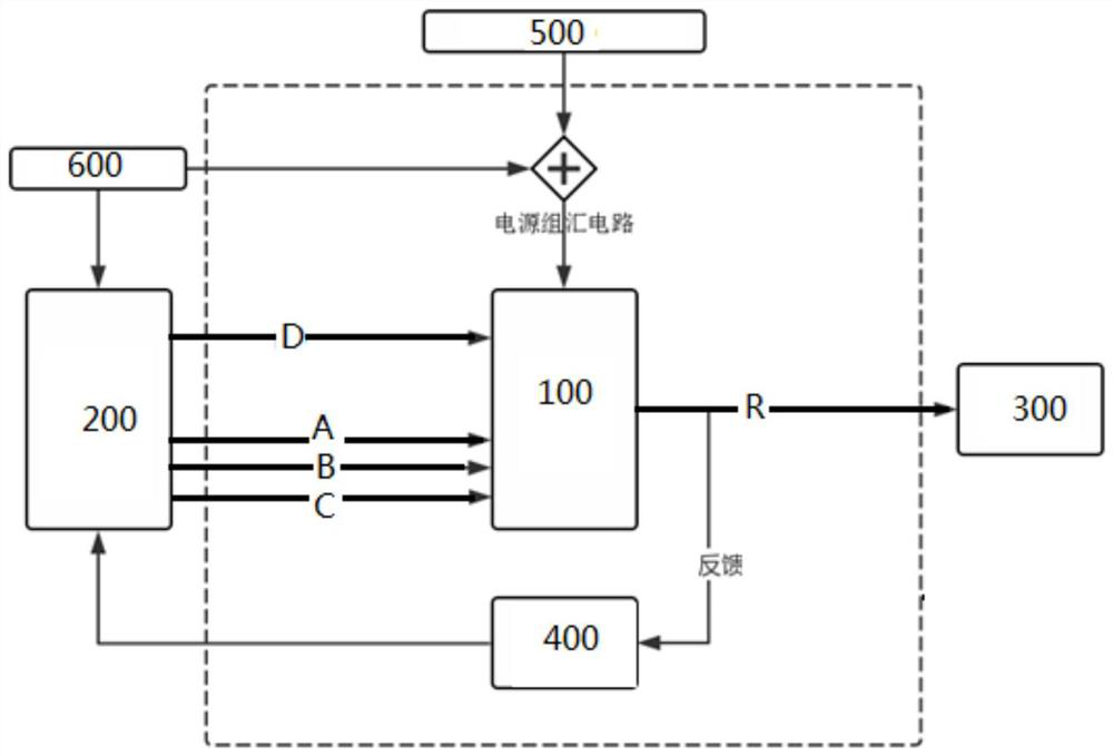
The invention discloses an electronic execution unit working state self-holding protection circuit and system. The self-holding protection circuit comprises an electronic execution unit working statesignal end, at least two logic signal input ends of the self-holding protection circuit, a logic operation circuit used for carrying out logic operation output on at least two logic input signals anda trigger circuit. By means of the logic operation circuit and the trigger circuit, the working state of the electronic execution unit working state signal end is not influenced when a microcontrolleris subjected to multiple transient anomalies. Even if an output signal of the microcontroller is abnormal, the working state of an execution unit is not influenced. When the microcontroller returns to normal, the working state of the current execution unit can be identified, and a correct control instruction is continuously given.

Description

Technical field [0001] The invention belongs to the protection technology of an industrial control electronic execution unit, and particularly relates to a self-maintaining control technology of the state of the electronic execution unit. Background technique [0002] In the field of industrial control, the working status of the electronic execution unit is the most important. Wrong execution may cause serious consequences. Especially in the automotive industry, the working status of the electronic execution unit is related to the safety of people and vehicles. A little carelessness can lead to tragic accidents that cause car crashes and deaths. For example, for the electronic system of a new energy vehicle, if the vehicle is running at a high speed, the relay execution unit of the high-voltage main circuit is disconnected due to the abnormality of the micro-control system, which will cause the entire vehicle to lose high-voltage power and cause the vehicle to lose control. [00...

Claims


Application Information

Patent Timeline
IPC IPC(8): G05B19/042
CPCG05B19/0423G05B2219/25257
Inventor 郑致远袁成保郑春阳
Owner 智新控制系统有限公司
Learn More