Circuit board processing and clamping treating device in production process of electronic parts

A production process, technology of electronic parts, applied in the field of circuit board processing clamping device, can solve the problem of unable to adjust the cutting angle, etc.

Inactive Publication Date: 2020-09-15
江西福昌发电路科技有限公司
View PDF7 Cites 2 Cited by
  • Summary
  • Abstract
  • Description
  • Claims
  • Application Information

AI Technical Summary

Problems solved by technology

[0004] The purpose of the present invention is to solve the disadvantage of the inability to adjust the cutting angle in the prior art, and propose a clamping device for circuit board processing in the production process of electronic parts

Method used


Image

  • Circuit board processing and clamping treating device in production process of electronic parts
  • Circuit board processing and clamping treating device in production process of electronic parts
  • Circuit board processing and clamping treating device in production process of electronic parts

Examples


Embodiment 1

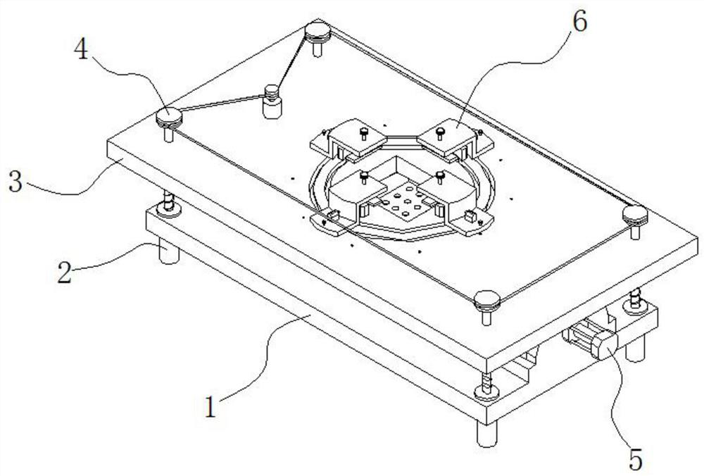
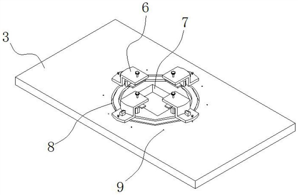
[0029] refer to Figure 1-4 , a circuit board processing and clamping device in the production process of electronic parts, including a base plate 1, a support mechanism 2 is installed at the four corners of the base plate 1, a processing plate 3 is fixedly installed on the top of the support mechanism 2, and a processing plate 3 is provided in the middle of the processing plate 3. The machining hole 7 is provided with a guide mechanism 8 outside the machining hole 7. The guide mechanism 8 includes a first annular groove 81, a second annular groove 82 and a straight groove 83. The second annular groove 82 is located at the inner ring of the first annular groove 81. , The straight groove 83 is opened between the first annular groove 81 and the second annular groove 82 .

[0030] Several clamping mechanisms 6 are installed in the first annular groove 81, and clamping mechanism 6 comprises arc-shaped guide block 62, and arc-shaped guide block 62 is installed in the first annular ...

Embodiment 2

[0034] refer to Figure 1-6 , as another preferred embodiment of the present invention, the difference from Embodiment 1 is that the support mechanism 2 includes a sleeve 21, the sleeve 21 is fixedly installed on the bottom of the bottom plate 1, and the top of the sleeve 21 is fixedly installed with a threaded sleeve 22, The inner thread of the threaded sleeve 22 is threaded with a threaded shaft 23, the threaded shaft 23 runs through the base plate 1, and extends to the inside of the sleeve seat 21; the top of the processing plate 3 is equipped with a transmission mechanism 4 corresponding to the threaded shaft 23, and the transmission mechanism 4 includes Four first pulleys 41, four first pulleys 41 are respectively fixedly installed on the top of the corresponding threaded shaft 23, the top of the threaded shaft 23 is fixedly installed with the processing plate 3, and one side of the first pulley 41 is provided with Motor 42, motor 42 is fixed on the top of processing plat...

Embodiment 3

[0037] refer to Figure 1-7 , as another preferred embodiment of the present invention, the difference from Embodiment 1 or Embodiment 2 is that a waste guide mechanism 5 is installed on the top of the bottom plate 1, and the waste guide mechanism 5 includes two parallel slide rails 51, and the two slide rails On the rail 51, a slide block 52 is slidably installed, a waste box 53 is fixedly installed on the top of the slide block 52, a fixed plate 54 is fixedly installed on one end of the slide rail 51, and a first cylinder 55 is fixedly installed on the outside of the fixed plate 54. The output end of the cylinder 55 is fixedly connected with the side wall of the waste box 53 .

[0038] By controlling the first cylinder 55, the waste box 53 slides outward along the slide rail 51, thereby leading out the waste inside the waste box 53, which is convenient for manual processing.


PUM


Abstract

The invention relates to the technical field of processing equipment of electronic parts, in particular to a circuit board processing and clamping treating device in the production process of the electronic parts. The circuit board processing and clamping treating device comprises a bottom plate, supporting mechanisms are correspondingly installed at four corners of the bottom plate, a processingplate is fixedly installed at the top ends of the supporting mechanisms, a processing hole is formed in the middle of the processing plate, a guiding mechanism is arranged on the outer side of the processing hole, and the guiding mechanism comprises a first annular groove, a second annular groove and a straight mouth groove; and a plurality of clamping mechanisms are installed in the first annulargroove, the clamping mechanisms comprise arc-shaped guiding blocks, sliding plates are fixedly installed at the tops of the arc-shaped guiding plates, installation plates are fixedly installed at oneends of the sliding plates, fixing bolts are installed at the other ends of the sliding plates in a threaded mode, adjusting bolts are connected to the tops of the installation plates in a threaded mode, pressing plates are fixedly installed at the bottoms of the adjusting bolts, and springs are arranged on the extension of the bottom ends of the adjusting bolts in a sleeving mode. According to the circuit board processing and clamping treating device, the cutting angle of parts can be adjusted, and waste materials are cleaned more conveniently.

Description

technical field [0001] The invention relates to the technical field of electronic parts processing equipment, in particular to a circuit board processing and clamping device in the production process of electronic parts. Background technique [0002] In the production process of electronic parts, it is often necessary to cut electronic parts, which requires laser cutting, and laser cutting uses a high-power density laser beam to irradiate the material, so that the material is quickly heated to the vaporization temperature, and evaporates to form holes. For the movement of the material, the holes continuously form a narrow slit to complete the cutting of the material; in the prior art, the clamping and positioning of the circuit board needs to be realized by a jig during laser cutting, and the existing one is used for the circuit board The clamping device for cutting is generally fastened by bolts. It is troublesome to install and disassemble it on the fixture, and the positi...

Claims


Application Information

Patent Timeline
IPC IPC(8): B23K26/70B23K26/16B23K37/04B23K26/38B23K101/42
CPCB23K26/16B23K26/38B23K37/0408B23K26/702B23K2101/42
Inventor 苏惠武赖剑锋张惠琳
Owner 江西福昌发电路科技有限公司
Why Eureka
Try Eureka