Auxiliary correction device for orthopedic spine
A spine and orthopedic technology, applied in the field of auxiliary correction devices, can solve the problems of uncomfortable correction of the spine, inability to adjust the correction angle, etc., and achieve a good correction effect
- Summary
- Abstract
- Description
- Claims
- Application Information
AI Technical Summary
Problems solved by technology
Method used
Image
Examples
Embodiment 1
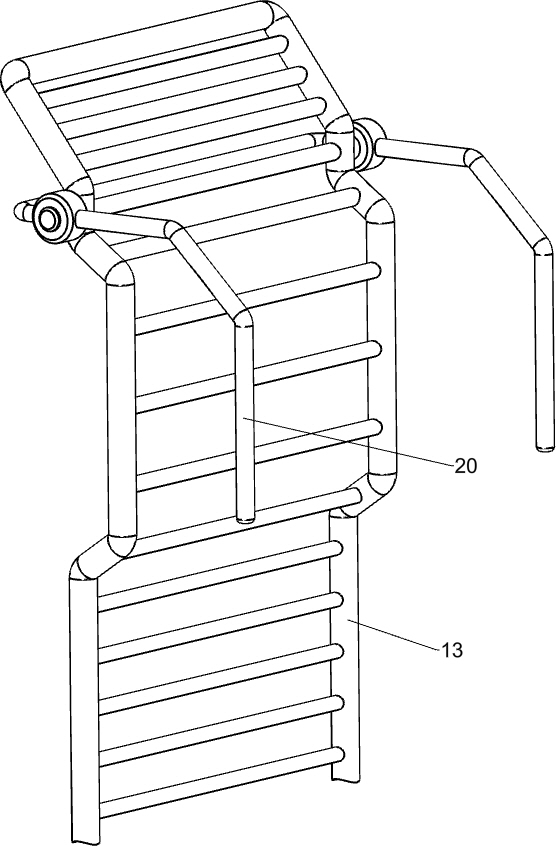
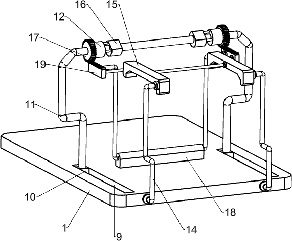
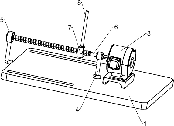
[0020] An auxiliary orthopedic device for orthopedic spine, such as Figure 1-4 As shown, it includes a base 1, a seat 2, a power assembly, a rectification assembly and an angle adjustment assembly. The seat 2 is slided on the right side of the top of the base 1, and the power assembly powered by a motor is provided in the middle of the top of the base 1. , the left side of the top of the base 1 is provided with a correcting component, and an angle adjustment component for changing the correcting angle by moving is provided between the correcting component and the base 1 .
[0021] When it is necessary to use the device to correct the spine, first, the person sits on the seat 2 and leans on the correction component with his back. At this time, the control power component starts to work, and the angle of the correction component is adjusted through the angle adjustment component, and the adjustment of the correction component is completed. After that, the control power unit sto...
Embodiment 2
[0023] On the basis of Example 1, such as Figure 1-5 As shown, the power assembly includes a reduction motor 3, a first support rod 4, a second support rod 5, a screw mandrel 6, a nut 7 and a connecting rod 8, and the bottom right side of the base 1 is fixed with a reduction motor 3 by bolts in the middle of the bottom right side. The output shaft on the left side of the motor 3 is connected with a screw rod 6 through a coupling, the right part of the base 1 is welded with a first support rod 4, the left side of the base 1 is welded with a second support rod 5, and the screw rod 6 and the first support rod 4 is rotationally connected with the second support rod 5, the screw rod 6 is screwed with a nut 7, the top of the nut 7 is welded with a connecting rod 8, and the connecting rod 8 is connected with the correction assembly.
[0024] When it is necessary to adjust the angle of the correction component, control the reduction motor 3 to rotate forward or reverse, drive the scr...
PUM
 Abstract
Description
Claims
Application Information
 - R&D Engineer
- R&D Manager
- IP Professional
- Industry Leading Data Capabilities
- Powerful AI technology
- Patent DNA Extraction
Browse by: Latest US Patents, China's latest patents, Technical Efficacy Thesaurus, Application Domain, Technology Topic, Popular Technical Reports.
© 2024 PatSnap. All rights reserved.Legal|Privacy policy|Modern Slavery Act Transparency Statement|Sitemap|About US| Contact US: help@patsnap.com


