
Neurological examination apparatus

An inspection device and neurology technology, applied in the field of neurology medical devices, can solve the problems of single function, inconvenience to carry, affecting work efficiency, etc., and achieve the effect of strong function

Pending Publication Date: 2020-09-15
LISHUI PEOPLES HOSPITAL
View PDF1 Cites 0 Cited by
  • Summary
  • Abstract
  • Description
  • Claims
  • Application Information

AI Technical Summary

Problems solved by technology

[0002] At present, the diagnosis of neurology diseases depends on accurate neurological examination, and the tools often used in neurology are percussion hammers, sensory inspection needles, etc. When you are in the room, you need to keep it in your hand all the time. Since the doctor still needs to carry the patient's case or other medical equipment, it will appear in a hurry and affect work efficiency.
[0003] For this reason, those skilled in the relevant technical fields have improved this, such as a kind of movable connection type neurology clinical diagnostic device disclosed in the Chinese patent application number CN201710849323.1, which discloses that the elastic band can be connected by connecting nuts and connecting bolts For installation and use, the device can also be used after removing the elastic band. The tapping head can be used to tap the patient through the spring, and the observation of the patient's reflex can help the doctor make a diagnosis. It is relatively simple to use, but the technical solution is still There are deficiencies, such as a single function, and the sensory test needle still needs to be carried separately, which is not conducive to doctors' use

Method used


Image

  • Neurological examination apparatus
  • Neurological examination apparatus

Examples


Embodiment Construction

[0017] In order to understand the technical scheme of the present invention more intuitively and completely, the non-limiting feature descriptions are as follows in conjunction with the accompanying drawings of the present invention:

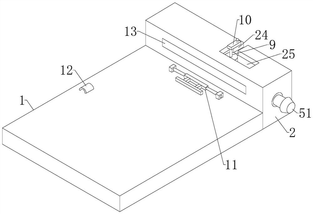
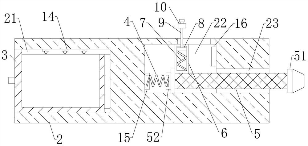
[0018] Such as figure 1 and figure 2 As shown, a neurology examination device includes a case splint 1, a test box 2 is fixed at the front end of the case splint 1, and the inner cavity of the test box 2 is provided with a drawer groove 21, an adjustment cavity 22 and a hammer handle in sequence from left to right Channel 23, the left side of the drawer groove 21 opens and inserts the inspection needle drawer 3, the adjustment chamber 22 communicates with the hammer handle channel 23, the right side of the hammer handle channel 23 opens, the drawer groove 21 and the hammer handle channel 23 are respectively located on the left and right sides of the inspection box 2 At both ends, the left side of the adjustment cavity 22 is provided with a wor...


PUM


Abstract

The invention discloses a neurological examination apparatus. The neurological examination apparatus comprises a case clamp plate, wherein an examination box is fixed at the front end of the case clamp plate; a drawer slot, an adjusting cavity and a hammer handle channel are sequentially arranged in an inner cavity of the examination box from left to right; an opening is formed in the left side ofthe drawer slot and an examination needle drawer is inserted into the opening; the adjusting cavity communicates with the hammer handle channel; a work spring is arranged at the left side of the adjusting cavity; the right end of the work spring is connected with a hammer handle; the right end of the hammer handle penetrates out of the hammer handle channel; an examination hammer head is arrangedat the right end of the hammer handle; a piston cylinder is fixed at the top of the hammer handle; a reset spring and a piston plate are accommodated into the piston cylinder; the piston plate is connected with a piston rod; a limiting rotary handle is fixed at the top of the piston rod; and a limiting groove and a moving groove are formed in the top of the examination box. The neurological examination apparatus can store a perception examination needle through the examination needle drawer, so that the perception examination needle is convenient for a doctor to take; and through the mode ofcombining the examination box with the case clamp plate, the neurological examination apparatus can serve as a case clamp and can also serve as an examination device when in use, so that the neurological examination apparatus has stronger functionality.

Description

technical field [0001] The invention relates to the technical field of neurology medical devices, in particular to a neurology inspection device. Background technique [0002] At present, the diagnosis of neurology diseases depends on accurate neurological examination, and the tools often used in neurology are percussion hammers, sensory inspection needles, etc. When you are in the room, you need to keep it in your hand all the time. Since the doctor still needs to carry the patient's case or other medical equipment, it will appear to be in a hurry and affect work efficiency. [0003] For this reason, those skilled in the relevant technical fields have improved this, such as a kind of movable connection type neurology clinical diagnostic device disclosed in the Chinese patent application number CN201710849323.1, which discloses that the elastic band can be connected by connecting nuts and connecting bolts For installation and use, the device can also be used after removing ...

Claims


Application Information

Patent Timeline
IPC IPC(8): A61B5/00A61B9/00A61B50/31B42F9/00
CPCA61B5/4005A61B9/00A61B50/31A61B2050/311B42F9/001
Inventor 赵丽萍冯继红虞伟妃蓝燕丽周珏伊吴秀英
Owner LISHUI PEOPLES HOSPITAL
Learn More