Method for eliminating current overshoot and switching circuit
A technology for switching circuits and currents, which is applied in the field of methods and switching circuits to eliminate current overshoots, can solve problems such as system reliability damage and current overshoots, and achieve the effects of improving service life, small damage, and eliminating current overshoots
- Summary
- Abstract
- Description
- Claims
- Application Information
AI Technical Summary
Problems solved by technology
Method used
Image

Examples
Embodiment 1
[0049] Such as Figure 5 , a method for eliminating current overshoot provided by the present invention comprises the following steps:
[0050] Determine whether the system enters the power-down state;
[0051]When the system enters the power-off state, the power-off protection device is activated, and the power-off timer starts to record the power-off time;
[0052] When the power-off time reaches a preset time, the integrator starts reverse integration, wherein the preset time is longer than the cycle time of the bus voltage VM.
[0053] Due to the power-off, the bus voltage drops, which makes the voltage of the sampling resistor drop, which in turn causes V ref and V fb As the difference increases, the integrator produces an error signal V comp will increase, causing the driver to generate a PWM signal that exceeds the steady-state value, and the output current I L Increasing the current beyond the steady state creates an overshoot.
[0054] Therefore, in this embodim...
Embodiment 11
[0058] On the basis of Embodiment 1, further optimization is made in this embodiment. Such as Figure 5 , a method for eliminating current overshoot provided by the present invention comprises the following steps:
[0059] Determine whether the system enters the power-down state;
[0060] When the system enters the power-off state, the power-off protection device is activated, and the power-off timer starts to record the power-off time;
[0061] When the power-off time reaches a preset time, the integrator starts reverse integration, wherein the preset time is longer than the cycle time of the bus voltage VM.
[0062] Due to the power-off, the bus voltage drops, which makes the voltage of the sampling resistor drop, which in turn causes V ref and V fb As the difference increases, the integrator produces an error signal V comp will increase, causing the driver to generate a PWM signal that exceeds the steady-state value, and the output current I L Increasing the current b...
Embodiment 2
[0069] Such as Figure 7 As shown, a method for eliminating current overshoot includes the following steps:
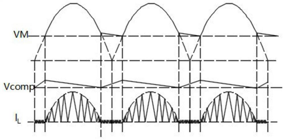
[0070] Obtain the bus voltage parameters, when the bus voltage is less than the power-off threshold voltage V PL , and the bus voltage continues to drop (such as Figure 6 As shown), at this time, it is determined that the system has entered a power-off state.
[0071] Start the power-down protection device, and the power-down timer starts to record the power-down time;
[0072] When the power-off time reaches a preset time, the integrator performs reverse integration, wherein the preset time is longer than the cycle time of the bus voltage VM.
[0073] When the reverse integration time of the integrator reaches, that is, when the reverse integration reaches 2, the integrator stops integrating until the system is powered on next time. The same reverse integration time can be any moment in Embodiment 1 to 2, and can also be greater than 2.
[0074] Due to the power...
PUM
 Abstract
Description
Claims
Application Information
 - Generate Ideas
- Intellectual Property
- Life Sciences
- Materials
- Tech Scout
- Unparalleled Data Quality
- Higher Quality Content
- 60% Fewer Hallucinations
Browse by: Latest US Patents, China's latest patents, Technical Efficacy Thesaurus, Application Domain, Technology Topic, Popular Technical Reports.
© 2025 PatSnap. All rights reserved.Legal|Privacy policy|Modern Slavery Act Transparency Statement|Sitemap|About US| Contact US: help@patsnap.com