Crystal bar constant angle bonding machine and constant angle bonding method thereof
A bonding method and bonding machine technology, which are applied to fine working devices, working accessories, manufacturing tools, etc., can solve the problems of fixed angle between crystal rods and material plates and low bonding accuracy, and achieve the effect of improving accuracy.
- Summary
- Abstract
- Description
- Claims
- Application Information
AI Technical Summary
Problems solved by technology
Method used
Image

Examples
Embodiment 1
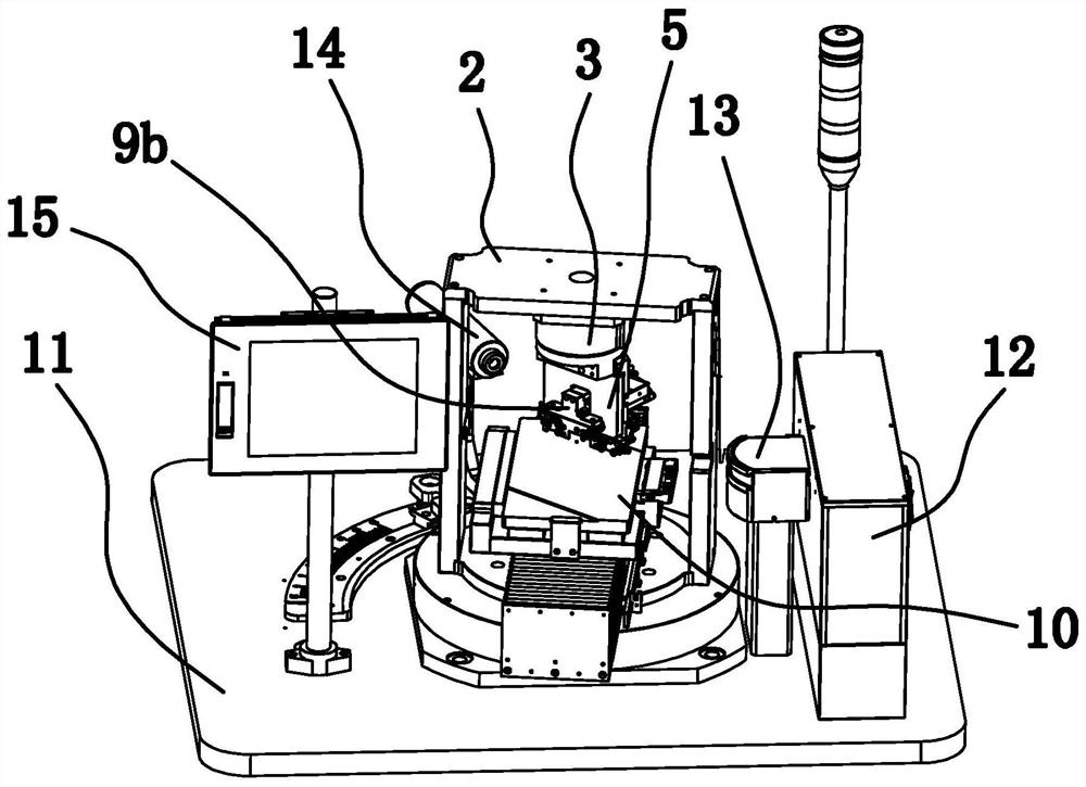
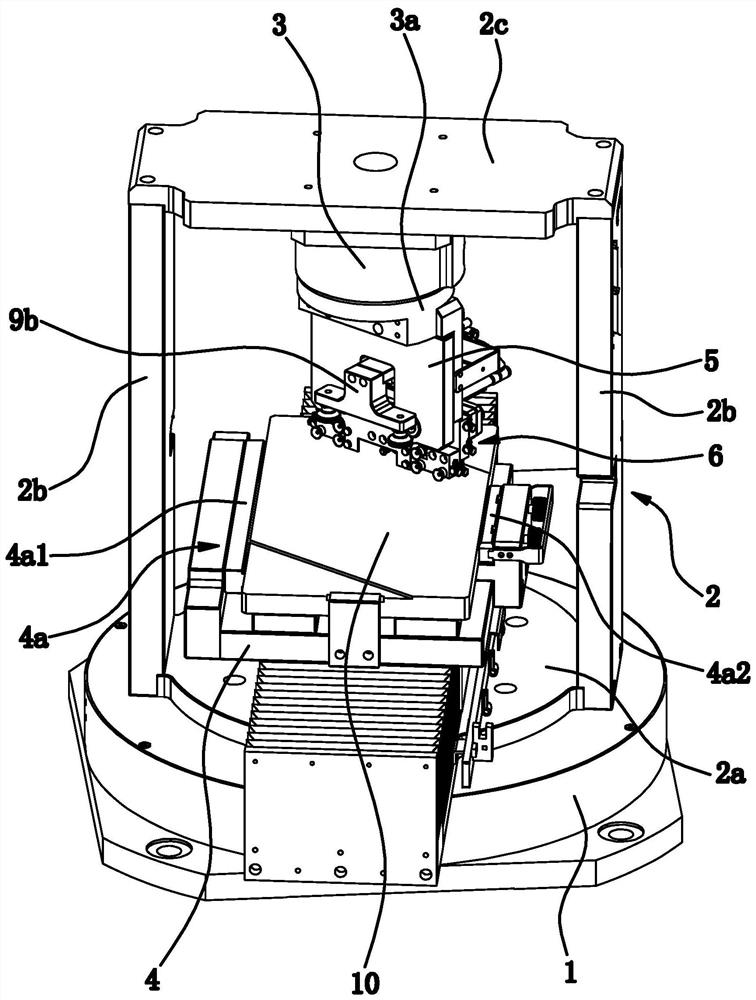
[0046] like figure 1 As shown, the crystal ingot fixed-angle bonding machine includes a workbench 11, a touch screen 15, an X-ray optical path emitting and receiving mechanism, a correction reference vertical plate 5 and a scanning frame 2 for horizontally placing and positioning the material plate 10, The touch screen 15 is arranged on the workbench 11, and the touch screen 15 is preset with a preset value representing a standard angle between the material plate 10 and the ingot and the allowable deviation range after the angle is fixed. The emitting and receiving mechanism of the X-ray optical path includes an X-ray box 12 , a monochromator 13 and a counter tube 14 , and the X-ray box 12 , the monochromator 13 and the counter tube 14 are all arranged on the workbench 11 . A scanning direct-drive motor 1 is fixed on the workbench 11 , and the scan frame 2 is located above the workbench 11 and connected to the rotating shaft of the scan direct-drive motor 1 . The scan direct-d...
Embodiment 2
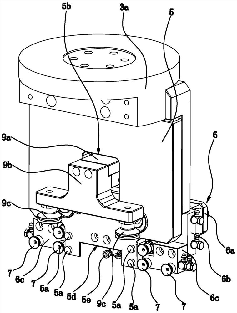
[0062] The structure of this embodiment is basically the same as that of Embodiment 1, the difference is: Figure 10-11 As shown, the flexible suction cup 7 is fixed on the correction reference vertical plate 5, the flexible suction cup 7 is an organ-shaped suction cup and can expand and contract along the direction perpendicular to the correction reference vertical plate 5, and the vertical cylinder 9 is located on the front side of the correction reference vertical plate 5 And it is connected with the pressing block 9b. After the organ-shaped suction cup sucks the crystal rod, it will shrink backward through the action of inertia, which is equivalent to the organ-shaped suction cup pulling the crystal rod backward, so that the crystal rod can be attached to the vertical reference plane of the correction reference vertical plate 5 Rely, cooperate with the pressing down of the pressing block 9b, so that the bottom surface of the ingot is attached to the upper surface of the ma...
Embodiment 3
[0074] The crystal rod fixed-angle bonding method is completed by using the crystal rod fixed-angle bonding machine in Embodiment 2, including the following steps:
[0075] A. Feeding: Place the material plate 10 horizontally on the clamp 4a of the scanning frame 2 and tighten the bolts on the clamp 4a so that the material plate 10 is fixed on the clamp 4a, and then place the ingot on the material plate 10, And the side of the ingot is as close as possible to the flexible suction cup 7 on the correction reference vertical plate 5 .
[0076] B. Correcting the fixed angle: click the run button on the touch screen 15, and the ingot fixed-angle bonding machine runs automatically.
[0077] b 1 1. Correct the flexible suction cup 7 on the reference vertical plate 5 to generate vacuum suction to suck the crystal rod. After the flexible suction cup 7 sucks the crystal rod, the corrugated portion will stretch and deform backward due to inertia, which is equivalent to a forward directi...
PUM
 Abstract
Description
Claims
Application Information
 - R&D
- Intellectual Property
- Life Sciences
- Materials
- Tech Scout
- Unparalleled Data Quality
- Higher Quality Content
- 60% Fewer Hallucinations
Browse by: Latest US Patents, China's latest patents, Technical Efficacy Thesaurus, Application Domain, Technology Topic, Popular Technical Reports.
© 2025 PatSnap. All rights reserved.Legal|Privacy policy|Modern Slavery Act Transparency Statement|Sitemap|About US| Contact US: help@patsnap.com