Wax oil smearing device for chair legs
A wax oil and chair technology, which is applied to the field of chair leg wax oil application devices, can solve the problems of large use of processing devices, low efficiency, labor consumption, etc., and achieve the effect of continuous supply.
- Summary
- Abstract
- Description
- Claims
- Application Information
AI Technical Summary
Problems solved by technology
Method used
Image
Examples
Embodiment 1
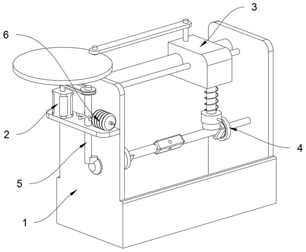
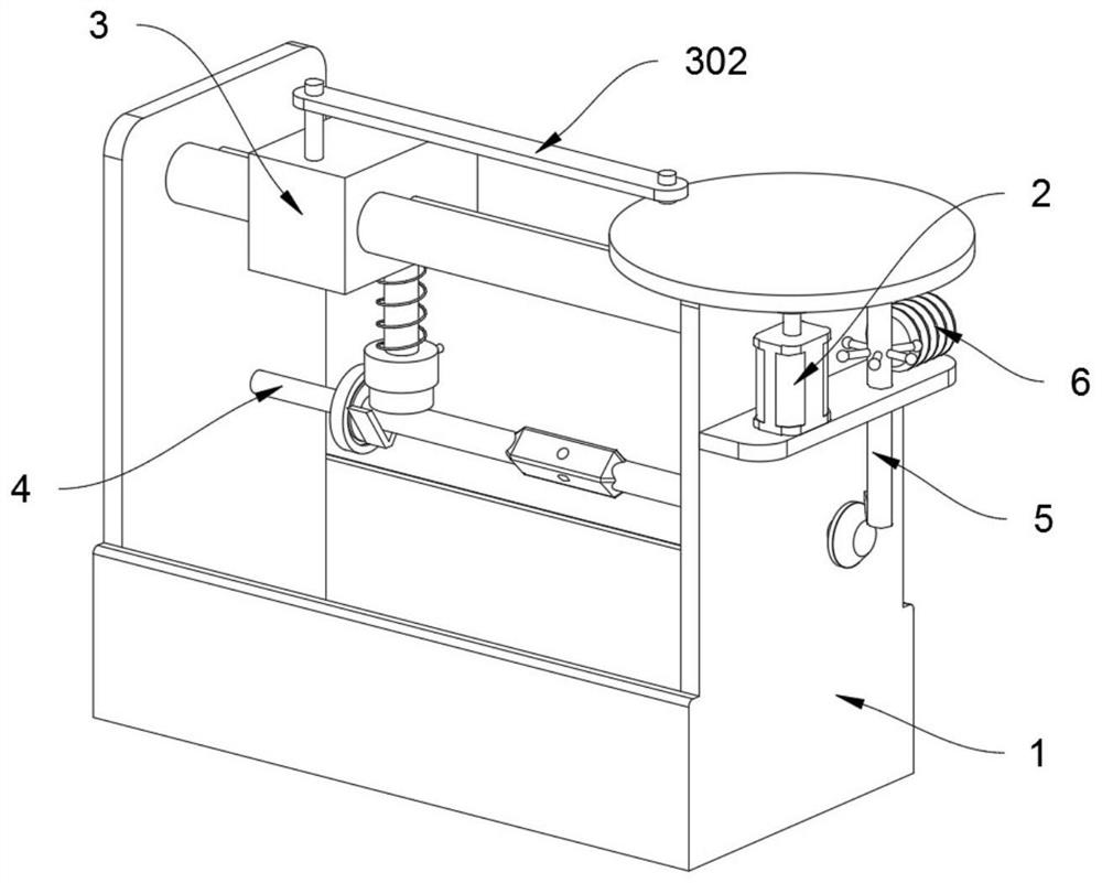
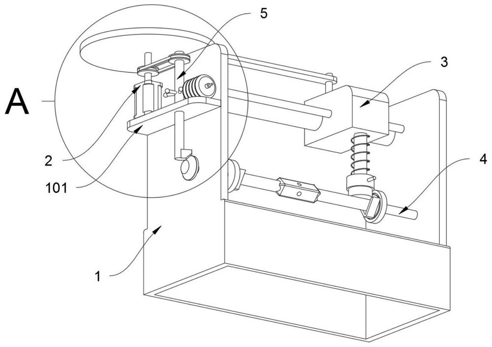
[0032] The invention provides a chair leg wax oil application device, refer to Figure 1-4 As shown, it includes a frame body 1, a motor fixing plate 101, a drive motor 2, a pulley A 201, a turntable 202, a brushing structure 3, a connecting rod 302, a table and chair leg fixing structure 4 and a transmission structure 5, and the structure of the frame body 1 A motor fixing plate 101 is installed on the upper part of the left wall, and a drive motor 2 is installed on the top rear side of the motor fixing plate 101. The middle upper part of the frame body 1 is slidably installed with a brushing structure 3 through a sliding shaft, and the bottom of the brushing structure 3 contains a suitable For the telescopic brushing head 301 of different chair legs, the top of the output shaft of the driving motor 2 is connected to the turntable 202, and the top of the turntable 202 is eccentrically connected to the connecting rod 302, and the right end of the connecting rod 302 is connected...
Embodiment 2
[0035] The invention provides a chair leg wax oil application device, refer to Figure 1-8 As shown, the table and chair leg fixing structure 4 includes a clamping head A401, a bevel gear 402, a clamping head B403 and a placement seat 404. The lower part of the left wall of the frame body 1 is rotatably connected with the clamping head A401, and the lower part of the right wall of the frame body 1 passes through The clamping head B403 is connected by threaded connection, the left end of the clamping head A401 passes through the left wall of the frame body 1, the left end of the clamping head A401 is connected with a bevel gear 402, and the bevel gear 402 is intermittently meshed with the transmission structure 5 for transmission. The right end of the tightening head A401 and the left end of the clamping head B403 are both rotatably connected with a placement seat 404, and the placement seat 404 is V-shaped.
[0036] The transmission structure 5 includes a rotating shaft 501, a...
Embodiment 3
[0040] The invention provides a chair leg wax oil application device, refer to Figure 1-4 As shown, it also includes toggle teeth 504 and wax oil pot 6, the bottom of the rotating shaft 501 is evenly spaced with toggle teeth 504, the top front side of the motor fixing plate 101 is equipped with wax oil pot 6, and the wax oil pot 6 passes through The pipeline is connected with the painting structure 3 .
[0041] When the rotating shaft 501 rotates, six toggle teeth 504 welded thereon in an annular array will also rotate accordingly, and the toggle teeth 504 can intermittently squeeze the wax oil pot 6 when rotating, thereby completing the supply of wax oil .
PUM
 Abstract
Description
Claims
Application Information
 - R&D Engineer
- R&D Manager
- IP Professional
- Industry Leading Data Capabilities
- Powerful AI technology
- Patent DNA Extraction
Browse by: Latest US Patents, China's latest patents, Technical Efficacy Thesaurus, Application Domain, Technology Topic, Popular Technical Reports.
© 2024 PatSnap. All rights reserved.Legal|Privacy policy|Modern Slavery Act Transparency Statement|Sitemap|About US| Contact US: help@patsnap.com


