
Automatic feeding, packaging and injection molding equipment and application method thereof

A technology of automatic feeding and injection molding equipment, applied in the field of injection molding, can solve the problems of color difference of non-ferrous injection molding parts, high labor intensity of workers, and error in mixing and weighting, and achieve the effect of accurate weighting, high degree of automation, and reduction of feeding times.

Inactive Publication Date: 2020-12-04
太仓市冬鑫塑料制品有限公司
View PDF7 Cites 2 Cited by
  • Summary
  • Abstract
  • Description
  • Claims
  • Application Information

AI Technical Summary

Problems solved by technology

[0002] With the advancement of science and technology and the improvement of industrial production levels, injection molded parts are more and more used in various fields, with broad market prospects. Most plastic injection molded parts are consumables, and in some occasions need frequent Therefore, there is a large demand for such injection molded parts and mass production is required; however, most of the existing injection molding production equipment requires manual step-by-step processing and production. There is a certain error in the weight of the mixed material, resulting in color difference in the colored injection molded parts

Method used


Image

  • Automatic feeding, packaging and injection molding equipment and application method thereof
  • Automatic feeding, packaging and injection molding equipment and application method thereof
  • Automatic feeding, packaging and injection molding equipment and application method thereof

Examples


Embodiment Construction

[0026] In order to explain the overall concept of the present invention more clearly, the following will be described in detail by way of examples in conjunction with the accompanying drawings.

[0027] In describing the present invention, it is to be understood that the terms "center", "upper", "lower", "front", "rear", "left", "right", "vertical", "horizontal", The orientation or positional relationship indicated by "top", "bottom", "inner", "outer", "axial", "radial" and "circumferential" are based on the orientation or positional relationship shown in the drawings, only It is for the convenience of describing the present invention and simplifying the description, but does not indicate or imply that the referred device or element must have a specific orientation, be constructed and operated in a specific orientation, and thus should not be construed as limiting the present invention.

[0028] In addition, the terms "first" and "second" are used for descriptive purposes only...


PUM


Abstract

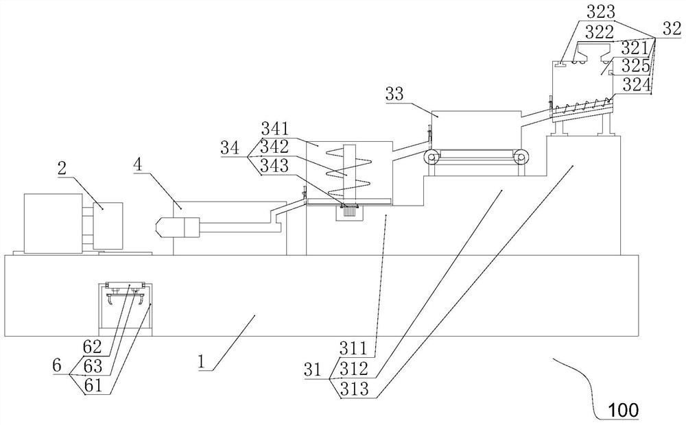
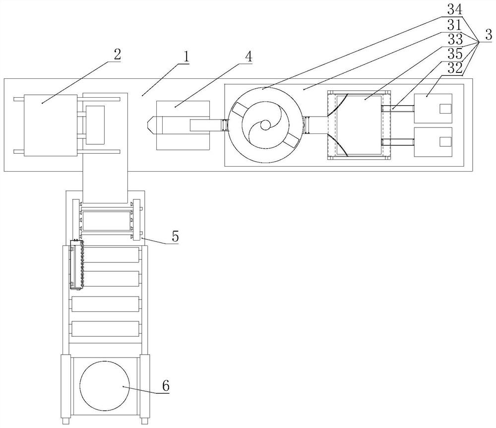
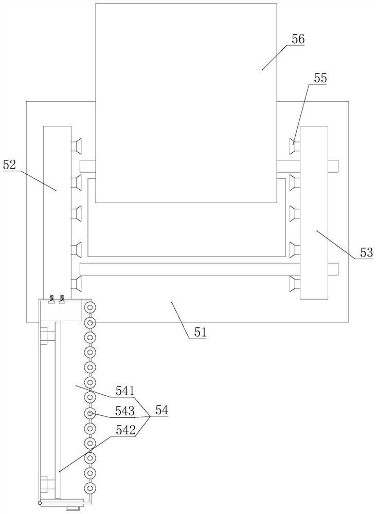
The invention discloses automatic feeding, packaging and injection molding equipment and an application method thereof. The automatic feeding, packaging and injection molding equipment comprises a mounting table, an injection mold, an automatic feeding device, an injection component and a receiving device; the injection mold is arranged on one side of the mounting table; the automatic feeding device comprises a mounting step, a dewatering and storing component, a weighing component, a mixing component and a conveying channel; the mounting step is arranged on the other side of the mounting table; the mounting step comprises a first step, a second step and a third step which are arranged from low to high; the mixing component, the weighing component and the dewatering and storage component are sequentially arranged on the first step, the second step and the third step; the injection component is arranged between the injection mold and the automatic feeding device; the receiving device comprises a base, a fixed frame, a movable frame, a bag storage component and a suction cup; the base is arranged on one side of the mounting table; the fixed frame and the movable frame are oppositelyarranged on the two sides of the base; the bag storage component is fixedly arranged on one side of the fixed frame; and the suction cup is arranged on the side, opposite to the movable frame, of thefixed frame.

Description

technical field [0001] The invention belongs to the technical field of injection molding, and in particular relates to an automatic feeding packaging injection molding equipment and a use method thereof. Background technique [0002] With the advancement of science and technology and the improvement of industrial production levels, injection molded parts are more and more used in various fields, with broad market prospects. Most plastic injection molded parts are consumables, and in some occasions need frequent Therefore, there is a large demand for such injection molded parts and mass production is required; however, most of the existing injection molding production equipment requires manual step-by-step processing and production. There is a certain error in the weight of the mixed material, which leads to the color difference of the colored injection molded parts. [0003] It should be noted that the above content belongs to the scope of the inventor's technical cognition...

Claims


Application Information

Patent Timeline
Patent Type & Authority Applications(China)
IPC IPC(8): B29C45/18B29C45/17B29C45/72B29C45/76B29B13/06B65B43/30
CPCB29B13/065B29C45/1769B29C45/1866B29C45/72B29C45/76B29C2045/0096B29C2945/7613B65B43/30
Inventor 沈冬明沈利明张萍
Owner 太仓市冬鑫塑料制品有限公司
Learn More