
Reciprocating coating equipment and coating method

A technology of coating equipment and coating cavity, which is applied in sputtering coating, ion implantation coating, vacuum evaporation coating and other directions, can solve the problems of high production cost, extremely poor economy, and many labors, and achieves an increase in the production cost. Competitive, well-structured, time-saving effects

Pending Publication Date: 2021-04-27
广东谛思纳为新材料科技有限公司
View PDF30 Cites 0 Cited by
  • Summary
  • Abstract
  • Description
  • Claims
  • Application Information

AI Technical Summary

Problems solved by technology

[0002] At present, most large-size substrates (more than 3 meters in length) coating equipment are divided into three types: horizontal continuous coating machine, vertical continuous coating machine and single type coating machine. If it is necessary to repeatedly coat the product back and forth (such as: AF / AS evaporation process), then although these two equipments can be realized, but because of the extremely low production capacity and the poor economy, this coating method will not be used
The third single-type coating machine is currently widely used coating equipment. Its disadvantage is that each furnace can only coat 2-3 pieces, and it uses a lot of manpower and low production capacity, resulting in high production costs.

Method used


Image

  • Reciprocating coating equipment and coating method
  • Reciprocating coating equipment and coating method
  • Reciprocating coating equipment and coating method

Examples


Embodiment

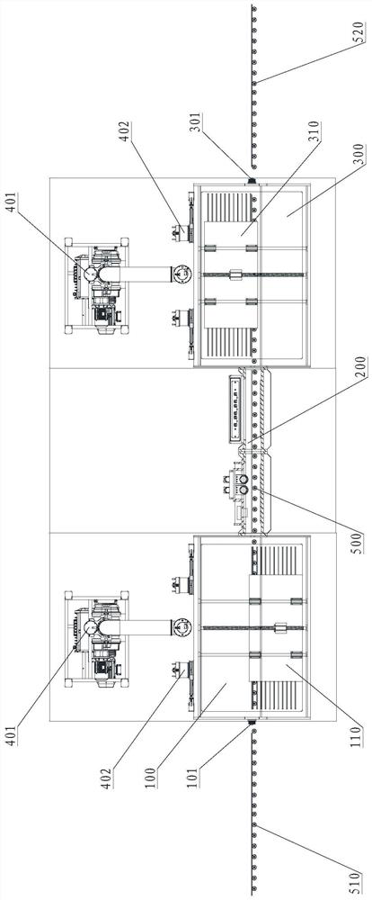
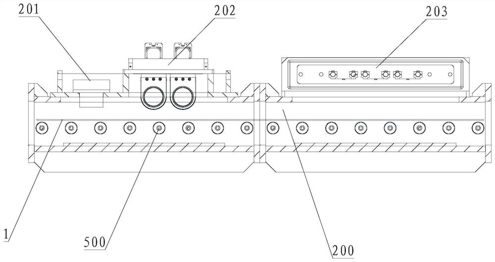
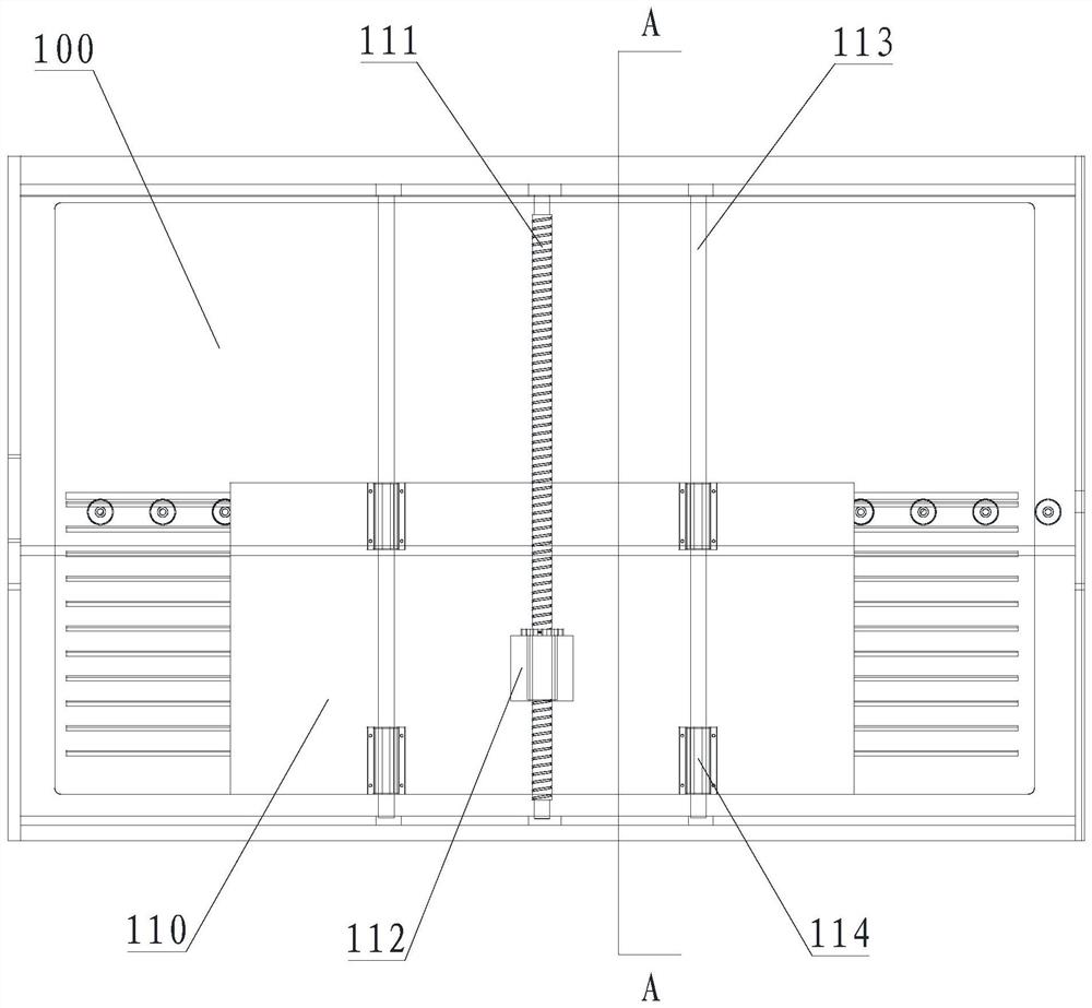
[0054] see Figure 1 to Figure 4 , a reciprocating coating device, including a first storage chamber 100, a coating chamber 200, a second storage chamber 300, a vacuum pump group and a conveying mechanism 500, the first storage chamber 100 communicates with the second storage chamber through the coating chamber 200 The cavity 300 is connected, and the transmission mechanism 500 passes through the first storage cavity 100, the coating cavity 200 and the second storage cavity 300 in sequence, and the entrance of the first storage cavity 100 is provided with a first vacuum isolation valve 101, and the The film feeding transport mechanism 510 is provided outside the film inlet of the first storage chamber 100, and the vacuum pump group is respectively connected with the first storage chamber 100 and the second storage chamber 300,

[0055] Both the first storage cavity 100 and the second storage cavity 300 are used to temporarily store the substrate 1;

[0056] The vacuum pump gr...


PUM


Abstract

The invention provides reciprocating coating equipment and a coating method. The reciprocating coating equipment comprises a first storage cavity, a coating cavity, a second storage cavity, a vacuum pump set and conveying mechanisms, the first storage cavity is communicated with the second storage cavity through the coating cavity, the conveying mechanism sequentially penetrates through the first storage cavity, the coating cavity and the second storage cavity, a first vacuum isolation valve is arranged at an inlet of the first storage cavity, and the vacuum pump set is connected with the first storage cavity and the second storage cavity. The coating equipment has the beneficial effects that the coating equipment is reasonable in structure and provided with the double storage cavities, multiple substrates can be conveyed back and forth through the conveying mechanisms in the two storage cavities, so that reciprocating coating of the substrates is achieved, the coating equipment is large in substrate loading amount, large in capacity and good in economic benefit, in the coating process, time waste caused by multiple times of vacuumizing is avoided, the production cost is effectively reduced, the production efficiency is improved, and the competitiveness of enterprises is improved.

Description

technical field [0001] The invention relates to the technical field of vacuum coating equipment, in particular to a reciprocating coating equipment and a coating method. Background technique [0002] At present, most large-size substrates (more than 3 meters in length) coating equipment are divided into three types: horizontal continuous type coating machine, vertical continuous type coating machine and single type coating machine. If it is necessary to repeatedly coat the product back and forth (such as: AF / AS evaporation process), then although these two equipments can be realized, but because of the extremely low production capacity and the poor economy, this coating method will not be used. The third kind of single-type coating machine is currently widely used coating equipment. Its disadvantage is that each furnace can only coat 2-3 pieces, and it uses a lot of manpower and low production capacity, resulting in high production costs. Contents of the invention [0003...

Claims


Application Information

Patent Timeline
Patent Type & Authority Applications(China)
IPC IPC(8): C23C14/56C23C14/24C23C14/34
CPCC23C14/566C23C14/568C23C14/24C23C14/34
Inventor 邵海平刘莉云曹英朝
Owner 广东谛思纳为新材料科技有限公司
Learn More