
High-temperature-resistant gas sensor and packaging method thereof

A gas sensor and high-temperature-resistant technology, which is applied in the direction of instruments, measuring devices, scientific instruments, etc., can solve the problems of deterioration, easy melting, and poor sealing of sensors, and achieve high temperature resistance, low cost, and easy storage.

Pending Publication Date: 2020-09-08
成都昶艾电子科技有限公司
View PDF6 Cites 1 Cited by
  • Summary
  • Abstract
  • Description
  • Claims
  • Application Information

AI Technical Summary

Problems solved by technology

Because the heat resistance of rubber parts is usually poor, it is easy to melt, deform or deteriorate under high temperature and long-term heat radiation, which makes the sealing of the sensor worse and affects the basic characteristics of the gas sensor.
The existing technology usually solves this problem by setting a heat insulation device between the rubber part and the sensor element, but it does not increase the withstand temperature of the entire sensor, which limits the application of this type of sensor in high temperature environments
The ambient temperature of flue gas emissions such as natural gas boilers is usually above 120°C. For such high-temperature environments, ordinary sensors using rubber parts cannot perform in-situ measurement

Method used


Image

  • High-temperature-resistant gas sensor and packaging method thereof
  • High-temperature-resistant gas sensor and packaging method thereof
  • High-temperature-resistant gas sensor and packaging method thereof

Examples


Embodiment 1

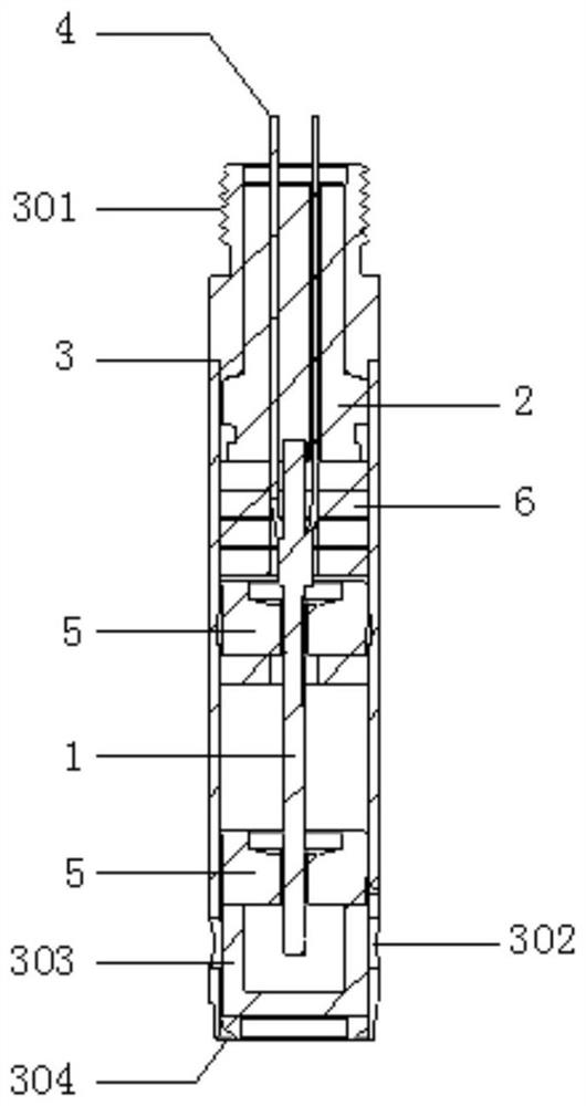
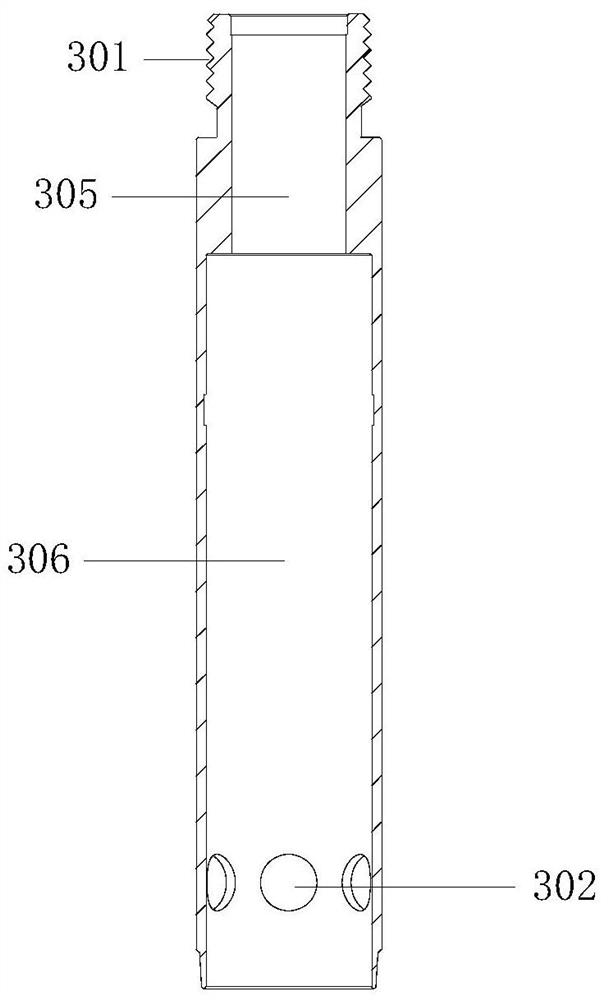
[0042] This embodiment provides a high temperature resistant gas sensor, such as Figure 1 to Figure 5 As shown, it includes a sensor element 1 and a casing 3. The sensor element 1 is placed in the casing 3. The sensor element 1 includes a detection end and an electrode end. The detection end of the sensor element 1 is used for gas detection. The extreme end is connected with a wire 4, and the inside of the sleeve 3 is provided with a first cavity 305 and a second cavity 306, and a lead device 2 is fixed in the first cavity 305, and the electrode end of the sensor element 1 and the lead device 2 Butt connection, the wire 4 connected to the electrode end is drawn out from the lead wire device 2, the second cavity 306 is used to place the sensor original 1, and a ceramic cake 6 and a ceramic pressure ring 5 are also arranged in the second cavity 306, the said The ceramic cake 6 fixes the electrode end of the sensor element 1 in the second cavity 306 , and the ceramic pressure ri...

Embodiment 2

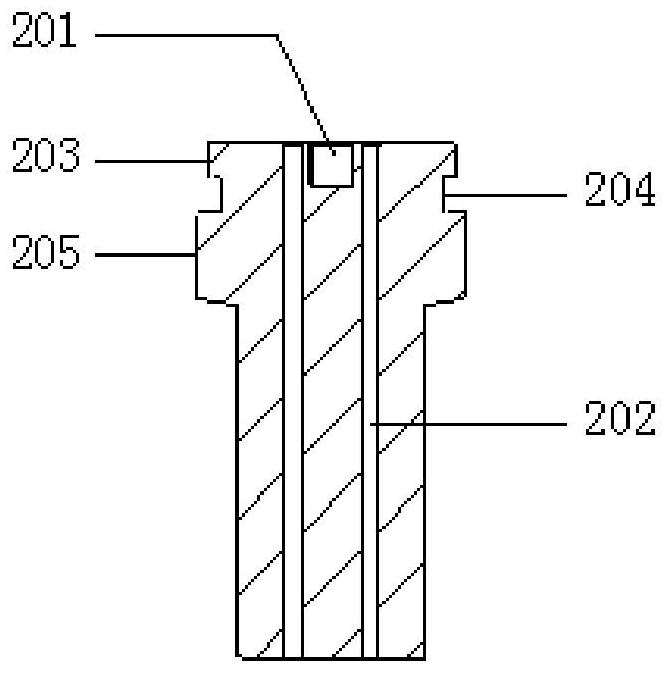
[0045] As an optimization to the above-mentioned embodiment, the lead wire device 2 is a cylinder, and a limit groove 201 is provided at the position where it abuts with the electrode end of the sensor element 1, and the electrode end of the sensor element 1 is fixed in the limit groove 201, and the lead wire device 2 A wire passing hole 202 runs through the inside of the wire along the axial direction, and the wire 4 is drawn out from the wire passing hole 202 . The size of the limiting groove 201 can be slightly larger than the electrode end of the sensor element 1, so that the end of the electrode end of the sensor element 1 is just placed in the limiting groove 201; the wire passing hole 202 is arranged on both sides of the limiting groove 201 Or around, its aperture is slightly larger than the diameter of the wire 4, and the number of wire passing holes 202 is the same as the number of electrodes of the sensor element 1. For ease of use, 6 wire passing holes 202 can be arr...

Embodiment 3

[0048] As an optimization of the above example, such as Figure 6 to Figure 7 As shown, the casing 3 is provided with a vent hole 302 on the outer wall of the end at one end of the second cavity 306, and a gas filter 303 is provided at the end of the second cavity 306 at the detection end of the sensor element 1 to filter the gas. The device 303 is a cup-shaped body with its open end facing the detection end of the sensor element 1 , covering the detection end of the sensor element 1 in the second cavity 306 , and the air hole 302 on the casing 3 facing the gas filter 303 . A sealing device 304 is provided outside the gas filtering device 303 , and the sealing device 304 fixes the gas filtering device 303 at the end of the second cavity 306 . The ceramic pressure ring 5 is provided with two, one of which presses and fixes the ceramic cake 6 on the electrode end of the sensor original 1, and the other is located in the second cavity 306 near the end of the sensor original 1 det...


PUM

PropertyMeasurementUnit
diameteraaaaaaaaaa

Abstract

The invention relates to the technical field of gas sensors, in particular to a high-temperature-resistant gas sensor and a packaging method thereof. The sensor comprises a sensor element and a sleeve, the sensor element is arranged in sleeve, the sensor element comprises a detection end and an electrode end; the detection end of the sensor element is used for gas detection; the electrode end of the sensor element is connected with a wire; a first cavity and a second cavity are formed in the sleeve; a lead device is fixed in the first cavity; the electrode end of the sensor element is in buttjoint with the lead device. A lead connected with the electrode end is led out of the lead device, the second cavity is used for containing the sensor element, a ceramic cake and a ceramic pressing ring are further arranged in the second cavity, the ceramic cake fixes the electrode end of the sensor element in the second cavity, and the ceramic pressing ring fixes the detection end of the sensor element in the second cavity. According to the invention, the sensor element can be fixed, insulated and sealed, has higher high-temperature resistance, and can be used in a high-temperature environment.

Description

technical field [0001] The invention relates to the technical field of gas sensors, in particular to a high temperature resistant gas sensor and a packaging method thereof. Background technique [0002] A gas sensor is a device that converts information such as gas composition and concentration into electrical signals that can be used by personnel, instruments, computers, etc. The basic characteristics of gas sensors, namely sensitivity, selectivity and stability, etc., are mainly determined by the choice of materials. Selecting appropriate materials and developing new materials can optimize the sensitive characteristics of gas sensors. [0003] Existing gas sensors, such as zirconia sensor elements used for gas analysis, usually use rubber parts as seals at the electrode ends, and lead wires are drawn out after passing through the rubber parts. Because the heat resistance of the rubber parts is usually poor, it is easy to melt, deform or deteriorate under high temperature...

Claims


Application Information

Patent Timeline
Patent Type & Authority Applications(China)
IPC IPC(8): G01N27/00B23K1/00
CPCG01N27/00B23K1/0016
Inventor 蒲友强
Owner 成都昶艾电子科技有限公司
Learn More