
Imaging device, SMA driving equipment, manufacturing method of SMA driving equipment and driving method of SMA driving equipment

A driving device and driver technology, which is applied in image communication, TV, color TV components and other directions, can solve the problems of short moving distance of camera lens assembly, slow corresponding moving speed of camera lens, and large moving stroke, etc. The effect of reducing the drive current and reducing the response time

Pending Publication Date: 2020-09-04
NINGBO SUNNY OPOTECH CO LTD
View PDF1 Cites 4 Cited by
  • Summary
  • Abstract
  • Description
  • Claims
  • Application Information

AI Technical Summary

Problems solved by technology

[0006] The SMA of the prior art still has at least one defect as the driver: First, the drive stroke of the SMA driver of the prior art is short, resulting in a short moving distance of the camera lens assembly driven by the SMA driver.
When it is necessary to adjust the focus, the SMA driver is energized to heat the SMA wire of the SMA driver, thereby moving the camera lens upwards, but this lens needs to be driven to move a relatively large distance, especially when needed When adjusting the camera lens to a high position, the SMA driver needs to move the camera lens from the lowest position to the highest position
The entire moving stroke is relatively large, resulting in slow movement of the camera lens

Method used


Image

  • Imaging device, SMA driving equipment, manufacturing method of SMA driving equipment and driving method of SMA driving equipment
  • Imaging device, SMA driving equipment, manufacturing method of SMA driving equipment and driving method of SMA driving equipment
  • Imaging device, SMA driving equipment, manufacturing method of SMA driving equipment and driving method of SMA driving equipment

Examples


Embodiment Construction

[0113] The following description serves to disclose the present invention to enable those skilled in the art to carry out the present invention. The preferred embodiments described below are only examples, and those skilled in the art can devise other obvious variations. The basic principles of the present invention defined in the following description can be applied to other embodiments, variations, improvements, equivalents and other technical solutions without departing from the spirit and scope of the present invention.

[0114] Those skilled in the art should understand that in the disclosure of the present invention, the terms "vertical", "transverse", "upper", "lower", "front", "rear", "left", "right", " The orientation or positional relationship indicated by "vertical", "horizontal", "top", "bottom", "inner", "outer", etc. is based on the orientation or positional relationship shown in the drawings, which are only for the convenience of describing the present invention...


PUM


Abstract

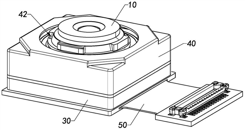
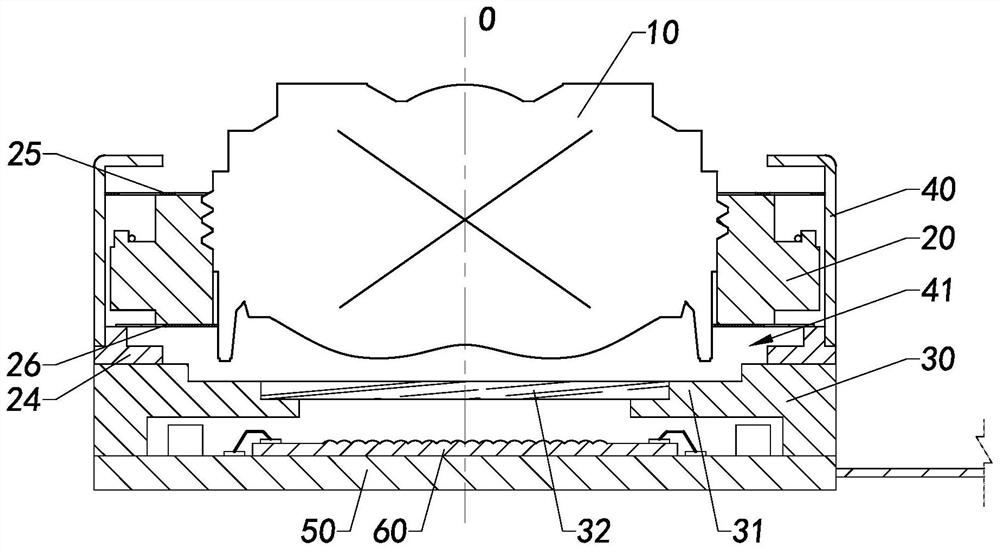
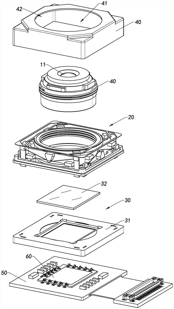
The invention provides a camera device, SMA driving equipment, a manufacturing method of the SMA driving equipment and a driving method of the SMA driving equipment. The camera device comprises at least one circuit board, a photosensitive chip, at least one lens, a lens base and at least one SMA driving equipment. The SMA driving equipment further comprises a lens carrier, at least one uplink driver and at least one downlink driver. The lens carrier is connected to the uplink driver in a driving manner. The uplink driver supports the lens carrier upwards in a thermal driving manner, and lifting the lens carrier to move upwards, wherein the lens carrier is drivingly connected to the downlink driver, wherein the downlink driver pulls the lens carrier downwards in a thermal driving mode and pulls the lens carrier to move downwards, the lens is arranged on the lens carrier of the SMA driving equipment, and the SMA driving equipment drives the lens to move up and down.

Description

technical field [0001] The present invention relates to an imaging device, in particular to an imaging device, an SMA driving device, a manufacturing method and a driving method thereof. Background technique [0002] With the increasing integration of mobile electronic devices such as mobile phones and tablet computers, the miniaturization of camera modules has become a development trend. At the same time, in order to meet the high-definition requirements of cameras, camera modules are required to be able to focus automatically. [0003] The prior art camera module with auto-focus function uses an electromagnetic drive motor to drive the lens assembly to a target position, so as to realize the auto-focus function. However, the driving mechanism of this prior art includes magnets, coils, etc., not only has a complex structure, but also increases the structure of the camera module, making it difficult to reduce the overall size of the module structure, which is not in line wit...

Claims


Application Information

Patent Timeline
Patent Type & Authority Applications(China)
IPC IPC(8): H04N5/225H04N5/232
CPCH04N23/50H04N23/57H04N23/55H04N23/54H04N23/67
Inventor 阙嘉耀涂洪德王启孙孝央周凯伦
Owner NINGBO SUNNY OPOTECH CO LTD
Learn More