


Quick Research
Generate reliable direction feasibility study reports for your R&D in just a few steps.

Technical Q&A
Discover and master advanced knowledge NOW. Basics, ideas, possibilities, all at once.

Find Solutions
As an expert in R&D theories, this can generate solutions to your technical problems instantly.

Evaluate Feasibility
Analyze your overall solution with one click, know your potential R&D risks in advance.

Monitor Landscape
Get weekly tech updates, stay abreast of the latest tech innovations and key insights.
Ethernet switching module
An Ethernet and transfer technology, applied in the field of communications, can solve the problems of inconvenient testing of automotive plastic optical fiber Ethernet, inappropriate for automotive plastic optical fiber Ethernet interface testing, etc., and achieve the effect of convenient testing
- Summary
- Abstract
- Description
- Claims
- Application Information
AI Technical Summary
Problems solved by technology
Method used
Image

Examples
Embodiment 1
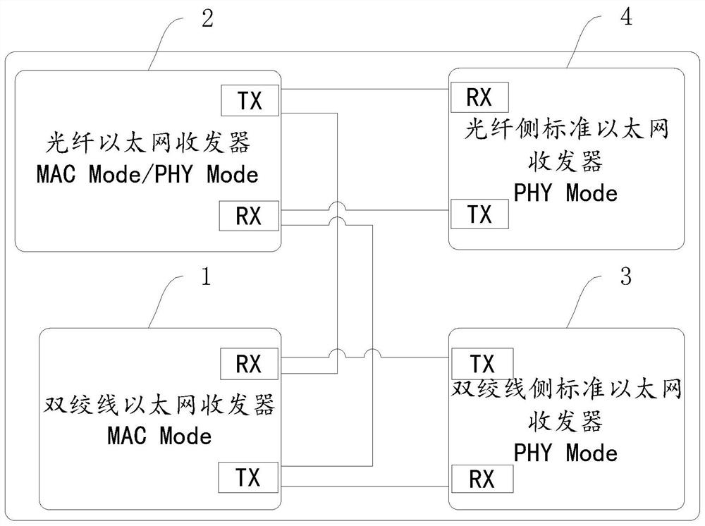
[0034] An Ethernet switching module, figure 1 A structural block diagram of an Ethernet switching module provided in Embodiment 1 of the present application is given, refer to figure 1 , the Ethernet conversion module includes a twisted pair Ethernet transceiver 1, a fiber optic Ethernet transceiver 2, a standard Ethernet transceiver 3 on the twisted pair side and a standard Ethernet transceiver 4 on the fiber side. In this embodiment, the twisted pair Ethernet transceiver 1 and the optical fiber Ethernet transceiver 2 are the automotive twisted pair Ethernet transceiver 1 and the automotive plastic optical fiber Ethernet transceiver 2 respectively.
[0035] Wherein, the data transceiving interface (TX interface and RX interface) of the optical fiber side standard Ethernet transceiver 4 is connected to the data transmitting interface (TX interface and RX interface) of the optical fiber Ethernet transceiver 2 . Specifically, the RX interface and the TX interface of the standar...
Embodiment 2
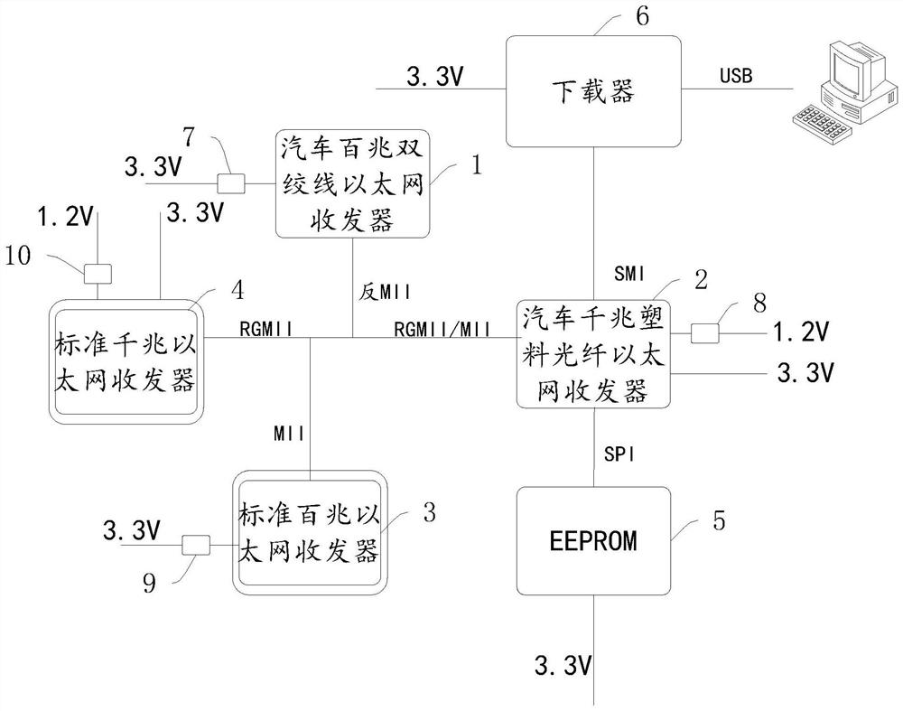
[0045] An Ethernet switching module, figure 2 A system block diagram of an Ethernet switching module provided in Embodiment 2 of the present application is given, and this embodiment provides further configuration of the Ethernet switching module on the basis of Embodiment 1.
[0046] refer to figure 2 , in this embodiment, the twisted-pair Ethernet transceiver 1, the optical fiber Ethernet transceiver 2, the twisted-pair side standard Ethernet transceiver 3 and the fiber-optic side standard Ethernet transceiver 4 are automotive 100M twisted-pair wires respectively Ethernet transceivers, automotive Gigabit plastic optical fiber Ethernet transceivers, standard 100M Ethernet transceivers and standard Gigabit Ethernet transceivers, the transceiver (network communication chip) models used can be selected according to actual needs.
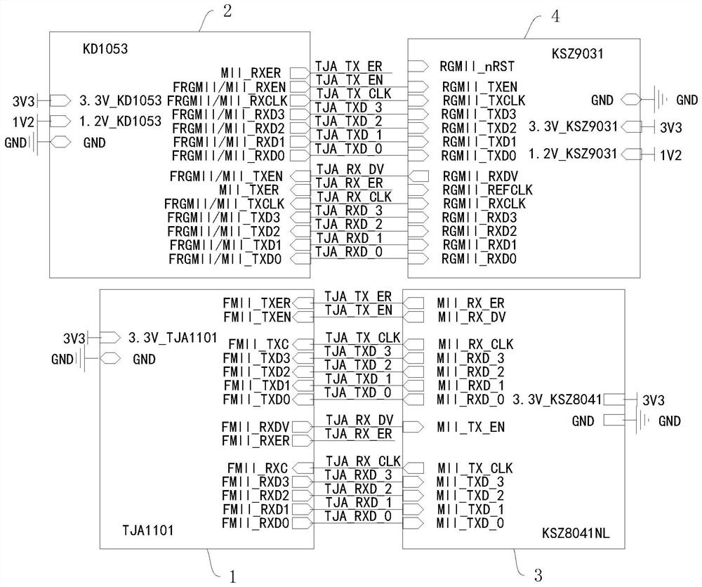
[0047] Exemplary, in this embodiment, the network communication chip models used in the automotive 100M twisted pair Ethernet transceiver, the auto...
PUM
 Abstract
Description
Claims
Application Information
 - R&D Engineer
- R&D Manager
- IP Professional
- Industry Leading Data Capabilities
- Powerful AI technology
- Patent DNA Extraction
Browse by: Latest US Patents, China's latest patents, Technical Efficacy Thesaurus, Application Domain, Technology Topic, Popular Technical Reports.
© 2024 PatSnap. All rights reserved.Legal|Privacy policy|Modern Slavery Act Transparency Statement|Sitemap|About US| Contact US: help@patsnap.com