
Heat dissipation device

A technology of heat sink and radiator, which is applied in the direction of electrical components, electrical solid devices, circuits, etc., can solve the problem that the flow of cooling medium is not easy to control constantly and so on.

Active Publication Date: 2020-09-04
ZHUZHOU CSR TIMES ELECTRIC CO LTD
View PDF2 Cites 0 Cited by
  • Summary
  • Abstract
  • Description
  • Claims
  • Application Information

AI Technical Summary

Problems solved by technology

[0004] In order to solve the technical problems in the prior art that the temperature of the cooling medium (water), the pressure of the cooling medium (water) and the flow rate of the cooling medium (water) are not easy to be constantly controlled, the present invention provides a cooling device, and the specific scheme is as follows:

Method used

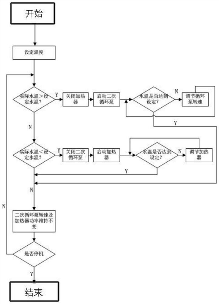
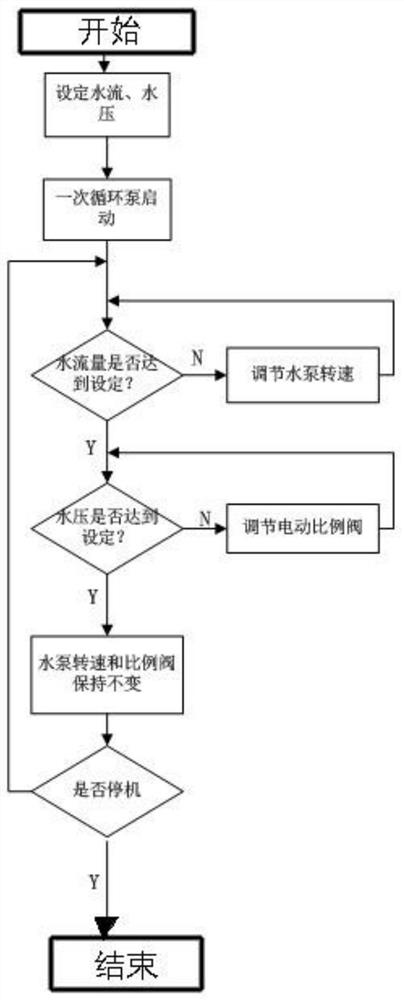

Image

  • Heat dissipation device
  • Heat dissipation device
  • Heat dissipation device

Examples


Embodiment Construction

[0030] The present invention will be further described below in conjunction with the accompanying drawings.

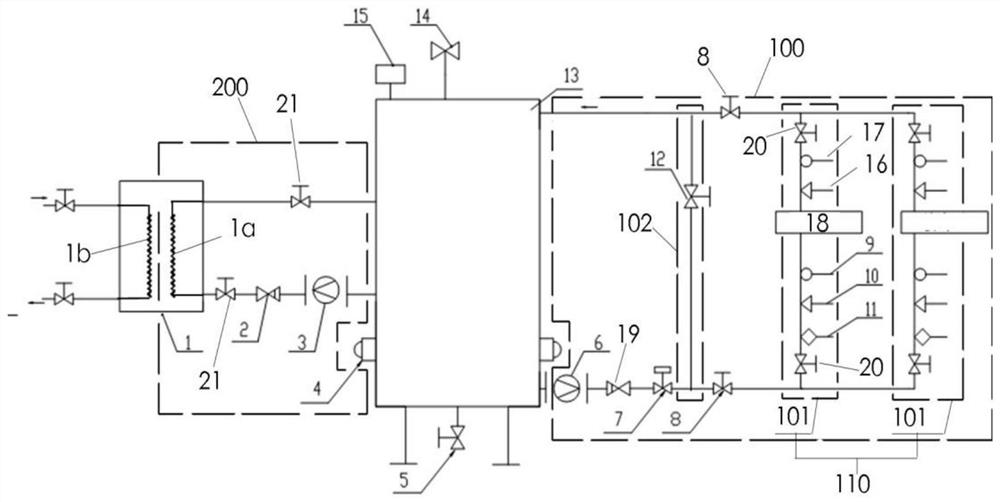
[0031] Such as figure 1 As shown, this embodiment provides a heat dissipation device, including a first circuit 100 and a second circuit 200 respectively connected to the medium container 13 for containing the first medium, the first circuit 100 and the second circuit 200 They are not connected to each other outside the medium container 13; wherein, the second loop 200 is used to adjust the temperature of the first medium in the medium container 13, and the first loop 100 is used to adjust the heat dissipation of the target device. The required flow rate and pressure of the first medium.

[0032] In the heat dissipation device of this embodiment, since the first circuit 100 and the second circuit 200 are not communicated with each other outside the medium container 13, when the second circuit 200 is used to adjust the temperature of the first medium and the first circ...


PUM


Abstract

The invention provides a heat dissipation device, which comprises a first loop and a second loop which are respectively connected with a medium container for accommodating a first medium, wherein thefirst loop and the second loop are not communicated with each other outside the medium container, the second loop is used for adjusting the temperature of a first medium in the medium container, and the first loop is used for adjusting the flow and the pressure of the first medium required by heat dissipation of a target device. According to the invention, the first loop and the second loop are not communicated with each other outside the medium container, so that when the temperature of the first medium is adjusted through the second loop and the flow and the pressure of the first medium areadjusted through the first loop, the first loop and the second loop can be independently adjusted and do not interfere with each other so as to keep the temperature, the flow and the pressure of the first medium constant.

Description

technical field [0001] The invention relates to the technical field of heat dissipation of heat generating devices, in particular to a heat dissipation device. Background technique [0002] During the working process of IGBT power components, IGBT devices will generate a lot of heat. One of the commonly used heat dissipation methods is to directly install IGBT devices on a water-cooled heat sink, and then introduce flowing cooling water into the water-cooled heat sink to dissipate the heat. go, so as to achieve heat dissipation. IGBT power components have extremely high requirements on heat dissipation conditions during some special requirements of the test process. It is required that the water temperature, water flow, and water pressure of the cooling water can be adjusted steplessly within a wide range, and can be kept constant within the set value range. [0003] Existing water-cooled heat sinks for power components generally have the disadvantages of a small adjustable...

Claims


Application Information

Patent Timeline
Patent Type & Authority Applications(China)
IPC IPC(8): H01L23/473H01L23/367
CPCH01L23/473H01L23/3672Y02D10/00
Inventor 刘敏安徐丽宾颜骥任亚东单媛黄达马瑶董洪海许志军卢圣文向华
Owner ZHUZHOU CSR TIMES ELECTRIC CO LTD
Learn More