
Terminal device for video editing artistic design

A technology for video editing and terminal devices, which is applied to coupling devices, components of connecting devices, calculations, etc. It can solve the problems of lack of dust-proof structure, difficult to find and clean, reduce the heat dissipation effect inside the terminal box, and improve the heat dissipation effect Effect

Inactive Publication Date: 2020-09-04
张红宾
View PDF9 Cites 4 Cited by
  • Summary
  • Abstract
  • Description
  • Claims
  • Application Information

AI Technical Summary

Problems solved by technology

[0006] In order to solve the above-mentioned technical problems, the present invention provides a terminal device for video editing art design to solve the following shortcomings in the actual use of existing terminal devices such as: 1. The existing terminal box is designed for internal electrical components For better heat dissipation, heat dissipation holes are usually provided on the left end surface and the rear end surface, and after a long period of use of the terminal box, the heat dissipation holes opened on it are very easy to attach a lot of dust and other debris, especially the rear end surface of the terminal box The heat dissipation holes opened are related to the air intake effect of the cooling fan, and it is difficult for people to find and clean these dust and other sundries in time, thereby reducing the heat dissipation effect inside the terminal box; 2. The USB on the front top of the existing terminal box Due to the lack of an effective dust-proof structure at the jacks and headphone jacks, the USB jacks and earphone jacks on the terminal box are easy to fall into dust, which affects the normal use of the USB jacks and earphone jacks.

Method used


Image

  • Terminal device for video editing artistic design
  • Terminal device for video editing artistic design
  • Terminal device for video editing artistic design

Examples


Embodiment Construction

[0026] Embodiments of the present invention will be further described in detail below in conjunction with the accompanying drawings and examples. The following examples are used to illustrate the present invention, but should not be used to limit the scope of the present invention.

[0027] as attached figure 1 to attach Figure 7 Shown:

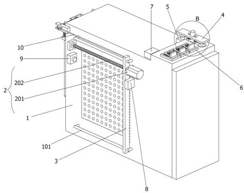
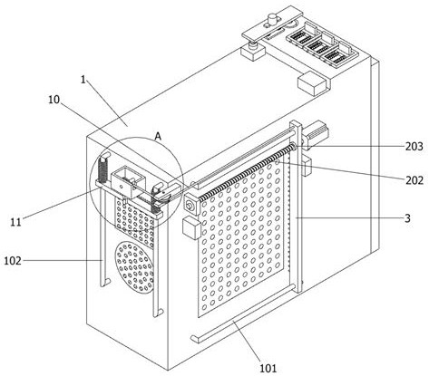
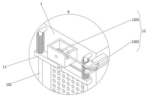
[0028]The present invention provides a terminal device for video editing art design, including a terminal box body 1, a drive mechanism 2 is installed on the left end surface of the terminal box body 1, the drive mechanism 2 includes a motor 201, a screw rod 202 and a nut 203, and the motor 201 is installed on the terminal The upper part of the left end surface of the box body 1, and the motor 201 is connected to the screw rod 202 through the rotating shaft, the other end of the screw rod 202 is externally equipped with a bearing, and the outside of the bearing is provided with a bearing block fixed on the left end surface of the terminal ...


PUM


Abstract

The invention provides a terminal device for video editing artistic design, which comprises a terminal box body, a driving mechanism is arranged at the upper part of the left end surface of the terminal box body, and the left end surface of the terminal box body is slidably connected with a first hairbrush which is longitudinally distributed. The first hairbrush matches a second hairbrush. By turning on a switch, a controller is enabled to start a motor, a motor rotating shaft drives a screw rod to rotate; a nut drives the first hairbrush to move backwards under the action of threads; when thefirst hairbrush moves to the rear end; a key on the reverse switch is pressed; the rotating shaft of the motor reversely rotates; and when the first brush moves to the front end, a key on the stop switch is pressed, so that the motor stops operating, the first brush can clean the heat dissipation holes in the left end surface of the terminal box body every time the terminal box body is started, and the heat dissipation effect in the terminal box body is further improved.

Description

technical field [0001] The invention belongs to the technical field of terminal devices, and more specifically relates to a terminal device for video editing and art design. Background technique [0002] The so-called terminal device for video editing art design is to edit and design the video. Video editing refers to the editing process of first recording the expected image with a camera, and then using video editing software on the computer to make the image into a disc. The above video editing There are many software such as VideoStudio. [0003] For example, application number: CN201720069351.7 The present invention discloses a terminal device for graphic design and video editing art design, including a graphic design main body, the graphic design main body is connected to the supporting base plate through a vertical support, and the vertical support is arranged in the middle There is a horizontal support, the front side of the graphic design main body is provided with ...

Claims


Application Information

Patent Timeline
IPC IPC(8): G06F1/18G06F1/20B08B1/00B08B17/04H01R13/52
CPCG06F1/182G06F1/20B08B17/04H01R13/5213B08B1/12B08B1/30
Inventor 张红宾
Owner 张红宾
Learn More