Dynamic Torque Tester for Crossed Roller Bearings for Harmonic Reducers

A technology of crossed roller bearings and harmonic reducers, which is applied in the direction of mechanical bearing testing, force/torque/power measuring instruments, and force sensors related to bearings. Low precision and other issues, to achieve the effect of compact structure, small footprint, and improved stability

Active Publication Date: 2021-12-14
ZHEJIANG LAIFUAL HARMONIC DRIVE COMPANY
View PDF7 Cites 0 Cited by
  • Summary
  • Abstract
  • Description
  • Claims
  • Application Information

AI Technical Summary

Problems solved by technology

During the specific test, pinch the outer ring of the crossed roller bearing with one hand and try to rotate the inner ring with the other hand. Whether it feels light or heavy, and whether the rotation is smooth and there is no stuck point in the whole circle is used as a sample product. Eligible basis, but relying on manual inspection alone has the disadvantages of strong randomness, low testing accuracy and low testing efficiency. When large-scale crossed roller bearings are manually tested continuously, the tester will consume a lot of physical strength

Method used


Image

  • Dynamic Torque Tester for Crossed Roller Bearings for Harmonic Reducers
  • Dynamic Torque Tester for Crossed Roller Bearings for Harmonic Reducers
  • Dynamic Torque Tester for Crossed Roller Bearings for Harmonic Reducers

Examples


Embodiment Construction

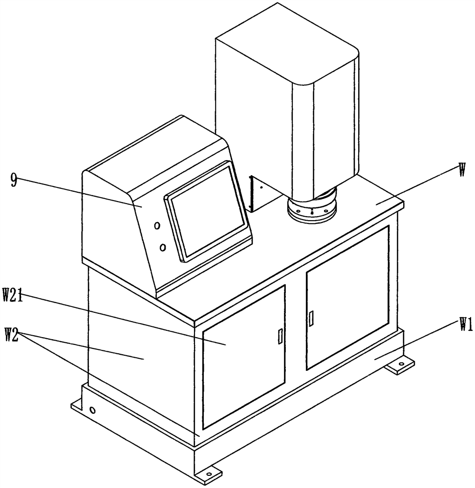
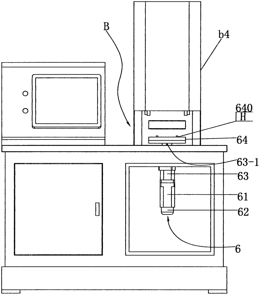
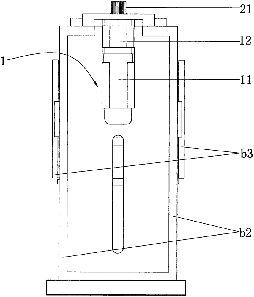
[0024] see Figure 1-7 As shown, the dynamic torque testing machine for crossed roller bearings for harmonic reducers includes workbench W, controllers 9 installed on the left and right sides of the workbench, body B, and a body cover set on body B. b4. Lifting deceleration motor, deceleration transmission mechanism, lifting mechanism, guiding mechanism, torque sensor, clamping mechanism and forward and reverse loading mechanism. Wherein, the fuselage B is mainly composed of two fuselage side panels b2 of the same shape and specifications and a fuselage roof b1 welded into a fuselage frame, and a partition (not shown) is welded between the two fuselage side panels, thereby Divide the fuselage B into a front fuselage and a rear fuselage. The outer walls of the side panels of the two fuselages respectively fix the guide rail mounting plate b3; the base W1 is set under the workbench W, and the cabinet W2 is connected between the base and the workbench. Two cabinet doors W21.

...


PUM


Abstract

The invention discloses a dynamic torque testing machine for a crossed roller bearing used in a harmonic reducer. The lifting reduction motor has an output shaft and is installed vertically on the rear body, and the lifting mechanism includes a vertical wire installed on the front body and connected by transmission threads The rod, the screw sleeve, the reduction transmission mechanism includes a toothed belt, the driving pulley fixed on the output shaft, the driven pulley fixed on the screw sleeve, the guiding mechanism includes a vertical guide rail and a moving beam slider part for fixing the upper end of the torque sensor , the clamping mechanism includes a balance beam suspended at the lower end of the torque sensor, a horizontal cylinder equipped with a reverse synchronous piston rod, a carriage arranged on both sides of the cylinder, jaws respectively connected to the carriage, and the connection of the two piston rods The end is connected to the carriage, and the free ends of the two piston rods correspond to the guide holes opened on the carriage facing the connected carriage. The forward and reverse loading mechanism includes a torque loading disc and a loading assembly with output shaft for its connection to make. The invention has a compact structure and overcomes the shortcomings of inefficient and rough testing.

Description

【Technical field】 [0001] The invention relates to a dynamic torque testing machine for a crossed roller bearing used in a harmonic reducer, and belongs to the field of dynamic torque testing equipment for a crossed roller bearing used in a harmonic reducer. 【Background technique】 [0002] In the prior art, the dynamic torque of the crossed roller bearing used in the harmonic reducer is tested by manually simulating the rotation. During the specific test, pinch the outer ring of the crossed roller bearing with one hand and try to rotate the inner ring with the other hand. Whether it feels light or heavy, and whether the rotation is smooth and there is no stuck point in the whole circle is used as a sample product. However, manual inspection alone has the disadvantages of strong randomness, low test accuracy and low detection efficiency. When large-size crossed roller bearings are manually inspected continuously, the physical strength of the tester is high. 【Content of inven...

Claims


Application Information

Patent Timeline
Patent Type & Authority Patents(China)
IPC IPC(8): G01M13/04G01L5/00
CPCG01M13/04G01L5/0009
Inventor 孙森陈雄风张杰杨燃张瀚
Owner ZHEJIANG LAIFUAL HARMONIC DRIVE COMPANY
Why Eureka
Try Eureka